Also try the other channel on the scope. You will have to set the trigger source to channel 2 if you use that one.
On both settings, 1x and 10x, I get less than 1V peak to peak from the Laser (below) – but it's another CD, one which really badly skips. Here on the 20mV / div setting.
With the original CD I got the 1.2V measurement from, it still is 1.2V (no pic shown). Obviously about 10% less dut to the scope's accuracy.

With the original CD I got the 1.2V measurement from, it still is 1.2V (no pic shown). Obviously about 10% less dut to the scope's accuracy.
It lights when I turn the VAR knob from its locked position.If that 'uncal' marking in red is a light it should not be lit.
Where did you get a photo of my scope? 🙂
I see you have the 'Var' control in an 'Uncalibrated' position. That Uncal light should be out.
The settings you are using of 20mv/div suggests you are in fact using a 10:1 probe. That divides the voltage by 10. Make sure the probe is compensated correctly using the Cal output. It only takes a few seconds to do. The trimmer is either in the probe body or the probe plug.
If it is set incorrectly it will make high frequency sine waves have the wrong amplitude on the scope.
I'll look in later 🙂

Yes, It sounds like your V axis is out of cal or the variable scale control is activated. The DVM will likely be more accurate and trustworthy in your situation. When you check the 5V to the MAB, put the scope in AC coupled input mode and pull up the vert scale to enlarge the amplitude for a better scale to reference.
The +2 rail is "ok" at 4.8V depending on the load, despite being on the lower end of tolerance. The noise is however a bit high (assuming your checking at the 5mV vert devision setting), specifically the type of noise with its dropouts is somewhat suspect. Try extending the time base a bit to see if there's onset of oscillation. I also don't like the dip in the eye pattern and the one in the 7805 output. Next step would also be to check the clock oscillator input to the MAB and its amplitude at the crystal next to it. That is also a reference for the DAC and DF on some of these players. Yours has the 14bit TDA1540 if Im not mistaken.
I'd replace the 7805 feeding the MAB including any decouplng caps after it. Use standard esr caps and make sure the ground is in place that goes to the front panel. The 2+ rail should be measured at the destination with its corresponding reference ground it sees ie right at the MAB chips B+ and ground. The display brightness will fluctuate if there is anything pulling on that 5V line. Current demand is very high in track seeking mode, but not on the 2+ rail, so if that one dips too low, it can indicate insufficient regulator current or another component drawing more than it should.
Attachments
I think it's one of the most beautiful troubleshooting session I've seen in a long time 😎
Good morning!I see you have the 'Var' control in an 'Uncalibrated' position. That Uncal light should be out.
The settings you are using of 20mv/div suggests you are in fact using a 10:1 probe. That divides the voltage by 10. Make sure the probe is compensated correctly using the Cal output. It only takes a few seconds to do. The trimmer is either in the probe body or the probe plug.
If it is set incorrectly it will make high frequency sine waves have the wrong amplitude on the scope.
I'll look in later 🙂
I had changed the setting to x10 after you mentioned it. (Which then, immediately out of my mind, confused me, as the readings were far to low... 10 times actually 🙂
I played around with the scope a bit yesterday, also used channel 2. It is not different from 1.
The VAR light comes on when I use the VAR knob in order to adjust the wave form to the grid on the screen, hence sort of calibrate it by hand.
I also tried the other, slightly more modern scope I have (has more bandwith and more resolution), but the risk that I don't get some settings is even greater there. Some new photos attached below. And the newer one makes a lot of fan noise.
Thank you. And let me thank @Mooly and @profiguy again for offering their brilliance and their decades-long experience. It is so great to find so much expertise so gently shared.I think it's one of the most beautiful troubleshooting session I've seen in a long time 😎
Seems a hard one, though. I should put this player back into the stash as it is eating up my time, and the spring term starts in some days... with lots of work ahead. so I will have to slow down troubleshooting unfortunately.
I'll post another shot of the +1 (12V) supply line ripple next.Yes, It sounds like your V axis is out of cal or the variable scale control is activated. The DVM will likely be more accurate and trustworthy in your situation. When you check the 5V to the MAB, put the scope in AC coupled input mode and pull up the vert scale to enlarge the amplitude for a better scale to reference.
The +2 rail is "ok" at 4.8V depending on the load, despite being on the lower end of tolerance. The noise is however a bit high (assuming your checking at the 5mV vert devision setting), specifically the type of noise with its dropouts is somewhat suspect. Try extending the time base a bit to see if there's onset of oscillation. I also don't like the dip in the eye pattern and the one in the 7805 output. Next step would also be to check the clock oscillator input to the MAB and its amplitude at the crystal next to it. That is also a reference for the DAC and DF on some of these players. Yours has the 14bit TDA1540 if Im not mistaken.
I'd replace the 7805 feeding the MAB including any decouplng caps after it. Use standard esr caps and make sure the ground is in place that goes to the front panel. The 2+ rail should be measured at the destination with its corresponding reference ground it sees ie right at the MAB chips B+ and ground. The display brightness will fluctuate if there is anything pulling on that 5V line. Current demand is very high in track seeking mode, but not on the 2+ rail, so if that one dips too low, it can indicate insufficient regulator current or another component drawing more than it should.
I measured the +2 (5V) line close to the MAB. Nothing pulled it down, no fluctuation of display lights.
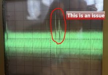
I checked at the 5mV div. Did you look at the video with the voltage sagging? I also have these spikes.
I have the TDA1540, right. Please tell me the exact points where to scope clock input and amplitude.
I have a L7805CV lying around here. In principle this should be usable as a drop-in-replacement, or not?
I admit that I have made the ESR of the power supply caps as low as possible when I changed them in 2020. Again, this worked well for 3 years. I even paralleled the electrolytics with film shunts... which I have removed now on the circuit side of the regulators (no change of course, the player skips happily along)
I am pondering if we are chasing ghosts here and all this comes down to a RAFOC bearing that needs to be lubricated and re-aligned (by some of the CD-X04 guys maybe who are running their cottage-industry modification businesses?). The player has pretty much worn out lettering so has seen quite a bit of use before I acquired it in 2020. Maybe I am wasting your time and brains and a mech guy would get this back working in 20 minutes with a drop of oil and a transparent disc with a line on it?
Could the spikes etc we see be the signs of mechanical problems?
I DID replace the 6240/6241 pair on the servo board before it connects to the motor board, just for kicks. I read from someone who did this although the pair of BD135/136 measured ok and through this cured his skipping problem. But no luck. I used 2SD669/SD649. I hope @Mooly won't tell me that I produced another Curé's egg. I could also put back the original ones.
And apologies for introducing potential error sources through my missing practice in using the scope. It's all a time issue, I just can't take half a day out to go through everything and really get into using the scope deeply. It's actually only my second time I use one (as @Mooly will remember from the first time I used one 🙂 )
I normally use Panasonic FC for most things. They are touted as "low ESR" but I think are standard enough to be used in this player?Yes, It sounds like your V axis is out of cal or the variable scale control is activated. The DVM will likely be more accurate and trustworthy in your situation. When you check the 5V to the MAB, put the scope in AC coupled input mode and pull up the vert scale to enlarge the amplitude for a better scale to reference.
The +2 rail is "ok" at 4.8V depending on the load, despite being on the lower end of tolerance. The noise is however a bit high (assuming your checking at the 5mV vert devision setting), specifically the type of noise with its dropouts is somewhat suspect. Try extending the time base a bit to see if there's onset of oscillation. I also don't like the dip in the eye pattern and the one in the 7805 output. Next step would also be to check the clock oscillator input to the MAB and its amplitude at the crystal next to it. That is also a reference for the DAC and DF on some of these players. Yours has the 14bit TDA1540 if Im not mistaken.
I'd replace the 7805 feeding the MAB including any decouplng caps after it. Use standard esr caps and make sure the ground is in place that goes to the front panel. The 2+ rail should be measured at the destination with its corresponding reference ground it sees ie right at the MAB chips B+ and ground. The display brightness will fluctuate if there is anything pulling on that 5V line. Current demand is very high in track seeking mode, but not on the 2+ rail, so if that one dips too low, it can indicate insufficient regulator current or another component drawing more than it should.
I used 56uF OS-CONs for the local filtering on the decoder board (following the OSC-CON craze some modifiers of CD-players have started). They should not be in the way here, or could they? as they are at the front end of the supply line. They also have their leads blackened after 3 years which is strange.
But again, all this worked well for three years and I did not touch anything before it started to go awry.
Fluke scope shots of the +1 (12V) rail to follow.
Ah btw...
I measured all voltages at the output of the regulators with a DVM yesterday night and they – you can already imagine – all measured ok within range. I can provide the numbers, but they really look good. In general slightly lower than in the manual (like 4.8V instead of 5V for +2 or -17.2V instead of -18.5V for -1 –– which had the greatest deviation).
I measured all voltages at the output of the regulators with a DVM yesterday night and they – you can already imagine – all measured ok within range. I can provide the numbers, but they really look good. In general slightly lower than in the manual (like 4.8V instead of 5V for +2 or -17.2V instead of -18.5V for -1 –– which had the greatest deviation).
Yes. just see my post directly above yours.just a question .
if I read correctly, you say that you completely recaptured your player, was it with quality capacitors?
I ask you this because 2 or 3 years ago I bought two boxes of capacitors of several values on Amazon "assortment from 1uF to 330uF" for the work of current use and in principle, I checked several of these values "to see" and at the end of the tests, I opened my trash can and put everything in it...
Not 100% sure of the quality of the OS-CONs (blackened legs), legit?
I did not get them from Mouser like the Panasonics.
Good question (but your post has vanished 🙂 )
I did not get them from Mouser like the Panasonics.
Good question (but your post has vanished 🙂 )
yes i tried to correct it but i screwed up when posting it 🙄Not 100% sure of the quality of the OS-CONs (blackened legs), legit?
I did not get them from Mouser like the Panasonics.
Good question (but your post has vanished 🙂 )
I had changed the setting to x10 after you mentioned it. (Which then, immediately out of my mind, confused me, as the readings were far to low... 10 times actually
The VAR light comes on when I use the VAR knob in order to adjust the wave form to the grid on the screen, hence sort of calibrate it by hand.
Once the light is on the scope is uncalibrated and the volts/div are then meaningless. You always have to measure the amplitude with it 'calibrated' (light off). The RF should then be around 1 to 1.2 volts peak to peak on the scope.
That means with a X10 probe and with the scope on 50mv/div the RF should fill two squares for 1 volt peak to peak amplitude and two squares and two small divisions for 1.2 volts peak to peak.
I am pondering if we are chasing ghosts here and all this comes down to a RAFOC bearing that needs to be lubricated and re-aligned (by some of the CD-X04 guys maybe who are running their cottage-industry modification businesses?). The player has pretty much worn out lettering so has seen quite a bit of use before I acquired it in 2020. Maybe I am wasting your time and brains and a mech guy would get this back working in 20 minutes with a drop of oil and a transparent disc with a line on it?
Could the spikes etc we see be the signs of mechanical problems?
Spikes are normal on any rail that is delivering a pulsed spiky load current. Amplitude matters of course but a few 10's of millivolts (bearing in mind you will not be using the exact correct grounds for measurement) is fine.
The bearing theory is possible. It would have to really 'stick' but I suppose that kind of issue could show as the arm moves so slowly in normal play. Its decades ago since I last played with these. Can you get at the bearing with a thin bit of wire etc to drip or wipe a bit of oil onto it?
Personally I would still look at replacing that laser drive transistor on the basis (again if it was me) that I have had them fail intermittently. More than once. Failure modes are weird. The mechanical 'shock' of the pickup skipping could be enough to heal something back up again. If it is a transistor with black corroded looking legs then that makes it suspect as well. Clutching at straws maybe but its a minutes job to swap it (be careful though if you do).
Another random thought. Does the player have an A-B repeat where you can select repeat between two points on the disc. If so does it skip if you have it on constant repeat between two known good points on a disc it will play.
I took the laser voltage measurement before I fiddled with the calibration setting, so it was calibrated. I also took it again with calibration switched on. So this seems to be fine
- Home
- Source & Line
- Digital Source
- Phillips CD 204 skipping 3 years after rebuild