They help to increase the rate at which the phase-angle of the feedback crosses through -180 degrees at the desired oscillation frequency. (They seem a little low in value though).
The CCT is made by Classd4sure. I forget where the thread is.
Are these capacitors (22pf) affecting the audio performance?
Are these capacitors (22pf) affecting the audio performance?
lumanauw said:Are these capacitors (22pf) affecting the audio performance?
No. Like Ouroboros said, they effectively lower the oscillation frequency and make it a little more stable. The value is pretty low and probably doesn't have much effect on the operation of the circuit. It should still work without those caps. Maybe they were just used to simulate stray input capacitance?
The released circuit of the UCD amplifier, as it appears in Bruno's patent and AES paper, only shows a simple pole-zero network for the feedback path. It is possible to enhance the performance of the amplifier by adding an extra HF pole to the feedback network. The circuit in the Hypex module has (as far as I know), these networks encased in epoxy resin. I don't know what feedback network Hypex use, but if you are used to doing Spice simulations, you can make a simple model of the forward and feedback paths of the amplifier to help you understand the optimum gain/phase characteristics of the feedback network.
Don't forget that you want the transition through -180 degrees to be at a fairly steep slope to provide a well defined oscillation frequency. If the slope as the loop-phase passes through -180 is at a very shallow slope, the performance will be sub-optimal.
Don't forget that you want the transition through -180 degrees to be at a fairly steep slope to provide a well defined oscillation frequency. If the slope as the loop-phase passes through -180 is at a very shallow slope, the performance will be sub-optimal.
Hello, BLMN,
Did you manage to clean out that sine wave ringing at the tops with the decoupling caps between +Vcc and -Vss?
Please post some comments on this, It happens to me too.
Best regards,
Pierre
Did you manage to clean out that sine wave ringing at the tops with the decoupling caps between +Vcc and -Vss?
Please post some comments on this, It happens to me too.
Best regards,
Pierre
Ouroboros said:Don't forget that you want the transition through -180 degrees to be at a fairly steep slope to provide a well defined oscillation frequency. If the slope as the loop-phase passes through -180 is at a very shallow slope, the performance will be sub-optimal. [/B]
Surely the 'shape' of the slope is determined by the frequency of the oscillation -- the higher the frequency, the steeper the slope? --- or have I missed the point.
Do these 22p caps described above actually act as the extra HF pole you mentioned ?
Pierre said:Hello, BLMN,
Did you manage to clean out that sine wave ringing at the tops with the decoupling caps between +Vcc and -Vss?
Please post some comments on this, It happens to me too.
Best regards,
Pierre
Hi Pierre,
I reduced the wave ringing rewiring the ground wires and decoupling the output devices using a 470nF/250V capacitor close to them at Vcc and Vss.
The grounds were splitted in two: one for decoupling and filter caps (470uF/100v on the board, near the output devices), and the other for signal and speaker out. I have bad results splitting the low and high level grounds, what I didn´t understand very well, but worked.
Both grouns are ended on a 16 awg bar connected on the center of the bulk output filter capacitors.
Another important question is the scope ground. I put the scope ground in the decoupling and filtering ground, using a isolated wire attached to the gruond pin of the scope, leaving the ground of the input isolated.
The ringing was greatly reduced.
I´m mounting the pcbs in the chassis. After finishing it I will show some waveforms here on this thread.
I hope it helps,
Best regards,
rogs said:
Surely the 'shape' of the slope is determined by the frequency of the oscillation -- the higher the frequency, the steeper the slope? --- or have I missed the point.
Do these 22p caps described above actually act as the extra HF pole you mentioned ?
It's the slope of the phase versus frequency part of the Bode plot I'm referring to. The rate-of-change of the phase as it crosses the -180 degree line is important for clean oscillation.
Ouroboros said:It's the slope of the phase versus frequency part of the Bode plot I'm referring to. The rate-of-change of the phase as it crosses the -180 degree line is important for clean oscillation.
Ah --sorry, I did miss the point! 🙂
If I understand correctly there are 3 components to the phase shift network - the output inductor, the lead network, and the propogation delay ----
I'm guessing that variations of inductor value designed to cut off say at 35KHz are not likely to make much difference at 400KHz -- and the propogation delay is sort of 'fixed' anyway, isn,t it?
So the lead network would appear to be the dominant variable, and as you say, Bruno's AES paper only hints at how to improve that with the adition of extra poles.
I've found it fairly easy to get my home made UCD working, based on the Philips App notes, -- and adding a differential input has made a huge improvement.
But comparing the output on the 'scope, under various load conditions, against the Hypex UCD180, has shown me just how far there is still to go.
No wonder Bruno buried his modulator in resin!!
Now to find something on adding a second pole to the network.......
UCD clones schematic usually has 2 opamps for differential input. I also found that this schematics are good for differential input, but has some problem when used with single RCA input (inverting input grounded)
Anyone has different input topology that is suitable for single input RCA?
Anyone has different input topology that is suitable for single input RCA?
I found the concept of a differential input helped a lot with the amplifier stability - and just because that gives you the option of using a balanced audio input signal, it doesn't have to be. Unbalanced is fine.
If you have a look at the 'technology' section on the main Hypex website, the very last paragraph makes that point.
So you can keep the advantage of the differential input for amplifier stability, and use your RCA signal input as well 🙂
If you have a look at the 'technology' section on the main Hypex website, the very last paragraph makes that point.
So you can keep the advantage of the differential input for amplifier stability, and use your RCA signal input as well 🙂
UcD vs. Hysteresis
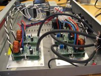
Just finished my project of comparing a UcD and a Hysteresis class-d amp, based on the same basic construction.
The construction was made to be as cheap and small as possible, but still delivering a good performance.
I think it is an interesting litle shootout.
Take a look at my homepage for more information 🙂
If anyone is interested I could post the Gerber files for the PCB.
The construction is really easy to get to work, and boards can be ordered directly from PCB companies like Olimex.
Attachments

Hi
Thank you for sharing gerbers. Now you can expact, that someone will build it, hopefully posted results here for use to see.
Thanks again.
Thank you for sharing gerbers. Now you can expact, that someone will build it, hopefully posted results here for use to see.
Thanks again.
ucd clip detection
Any body known how get clip signal from amplifier based on philips application note?
Any body known how get clip signal from amplifier based on philips application note?
Simplest way would be to use an IOC circuit.
Compare the input with the output, add a 40mS pulse stretcher (minimum pulse width your eye can see), and an indicator lamp of some sort.
Compare the input with the output, add a 40mS pulse stretcher (minimum pulse width your eye can see), and an indicator lamp of some sort.
Hi! Im new here, basicaly search and read on this section and SMPS section.
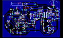
Im try to implement a UcD amplifier based on Philips manual and I spend some hours making a first layout for a single layer PCB and common components (no-SMD). My first layout work!!! Poor layout but play respectable sound. But mosfets runs hot, very hot.
My corrected layout is above. Sugestions are welcome.
Do you any candidate to substitute BC640 as turn-off buffer?? (easy to find and cheap please!).😀
Sorry my bad english!
Attachments
- Status
- Not open for further replies.
- Home
- Amplifiers
- Class D
- Philips UCD application note