TOINO said:Sorry…I can’t help everybody.
Now you know the equipment references. That is the difficult part.
Last night I have found another one with UCD, but have not the schematic.
They call the amplifier module CUD-S400. It is what is marked on pcb.
The output transistors are 2SK3607-01MR
Turn off transistors 2SA1954
Drv BC857CW
Gate diodes BAS316.
Cascodes between comparator and driver 2SC2713
Input BC856BW
Suply regulated SMPS +44V -44V
YAMAHA portable Pa system “STAGEPAS 500”
I find it interesting that a system consumes 65w of power and outputs 500w of power?? how does that work!
Philips FWM730 service manual. Size 34mB
http://rapidshare.com/files/47100154/Philips_FWM730_service_manual.rar
http://rapidshare.com/files/47100154/Philips_FWM730_service_manual.rar
tawn10 said:
I find it interesting that a system consumes 65w of power and outputs 500w of power?? how does that work!
Strange times my friend…
The market has so many of these miracles as the hell of good wills.

I think that the built-in amplifier is actually 2x200Wrms@4 ohms and 2x120Wrms@8 ohms, assuming that the SMPS can handle those power levels continuously (but it probably can't as continuous operation at full power is not required at all with music).
On the other hand, they don't specify the nominal impedance of the loudspeakers, but it may easily be 8 ohms so that an optional second pair can be added... Could you enlighten us about that, Toino?
Anyway, it must be noted that a 2x200W SMPS class D system can easily play music at clipping threshold while drawing only 65W or less. In comparison, a traditional class AB system with stone age 😀 power supply would be probably drawing 265W and wasting 200W as heat...

Philips released its UCD application note.
The UcD concept was patented by Philips. However, the use of the IP is granted (without a license fee) to third parties that use the enabling semiconductor components from Philips Semiconductors in their application.
Where did you get that info? I've googled a lot but nothing came up...
Are you sure the rights are philips property and not hypex property since they hired the inventor?
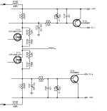
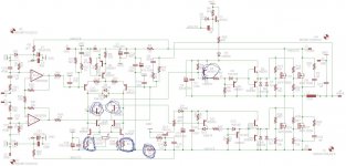
-------------------------------------------------------In this DIY UCD, in the input differential, there are capacitors C42-C44 valued 22pf connected to ground.
What is the function of these capacitors?
the function of these two capacitors is to suppress the Glish due to the junction of the diode (behavior with high frequency signals).
Hi,
C40-C45 (22pF) also have the same function.
This interpretation has been looking at the schematic on this thread.🙂
C40-C45 (22pF) also have the same function.
This interpretation has been looking at the schematic on this thread.🙂
Where did you get that info? I've googled a lot but nothing came up...
Are you sure the rights are philips property and not hypex property since they hired the inventor?
The quote comes from the Philips app note, dated March 2006, titled "LV MOSFET applications". Philips/NXP hold the rights to the patent, even though it is in Bruno's name. I checked this with NXP over two years ago, specifically because I needed to check the requirements for commercial use of the patent.
The quote comes from the Philips app note, dated March 2006, titled "LV MOSFET applications". Philips/NXP hold the rights to the patent, even though it is in Bruno's name. I checked this with NXP over two years ago, specifically because I needed to check the requirements for commercial use of the patent.
Thanks. I know I did not invent this license agreement myself, but I could not find it back. You're right, it was in that application note. I just didn't save a copy.
Thanks. I know I did not invent this license agreement myself, but I could not find it back. You're right, it was in that application note. I just didn't save a copy.
That app-note seems to have disappeared from the NXP web site now. I still have an electronic copy if anyone wants to see exactly what it said.

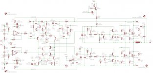
Values of components are the same as on the orginal schematic (except transistors) but his names are diffrent.
Is it a good idea to use 2N5401 for driving mos-fet? (driver -Q6, Q9 on my schematic)
I cant buy orginal parts and I'd use other parts, or make amp on IRS2092, but i don't know which will be better and cheaper.
Is it a good idea to use 2N5401 for driving mos-fet? (driver -Q6, Q9 on my schematic)
I cant buy orginal parts and I'd use other parts, or make amp on IRS2092, but i don't know which will be better and cheaper.
Last edited:
For Q6 and Q9 better choices would be BC369 or BC807.
2N5401 is fine for Q8 and Q10.
why are these bc369 better😕
Or a better low VCEsat (biss) transistor such as PBSS5140T or 5240T or similar transistors would be an option.why are these bc369 better😕
PBSS5240T pdf, PBSS5240T description, PBSS5240T datasheets, PBSS5240T view ::: ALLDATASHEET :::
hi whortless i have made the below schema but q13,14,3 & 21 plus the aux +12v section fails vltg is ir2110 smps +/- 55vlts but my outputs fets are o.k . what is my error?
diysmps
diysmps
Attachments
- Status
- Not open for further replies.
- Home
- Amplifiers
- Class D
- Philips UCD application note