No, I have not built this specific Delta-Sigma Class D amp yet. My designs are rather different to this. From the photo, it looks like aluminium-oxide.
In a past thread Bruno mentioned that it was a ceramic (alumina oxide) insulator.
http://www.diyaudio.com/forums/showthread.php?postid=487903#post487903
http://www.diyaudio.com/forums/showthread.php?postid=487903#post487903
ok, some testing:
to-220, capacitance (drain)case--heatsink
to220+mica+grease: 70pf
to220+mica : 27pf
to220+silpad: 11pf
to220+ceramic: 5pf
ceramic is alu.ox. , 1,5mm thick
to-220, capacitance (drain)case--heatsink
to220+mica+grease: 70pf
to220+mica : 27pf
to220+silpad: 11pf
to220+ceramic: 5pf
ceramic is alu.ox. , 1,5mm thick
Hi, Alfsch,
Thanks for the test 😀 I think I will use silpad (I can buy them here).
Complemenary mosfet class D (Pch+Nch) seems will not experience this effect, since all Drains are DC.
Thanks for the test 😀 I think I will use silpad (I can buy them here).
Complemenary mosfet class D (Pch+Nch) seems will not experience this effect, since all Drains are DC.
I read somewhere that for highside 12V supply better use bootstrapp compared to using floating 12V from transformer.
What happens if I use floating 12V for highside 12V supply?
What happens if I use floating 12V for highside 12V supply?
Hi, Alfsch,
I measure some insulation material. Maybe my capacitance-meter is not too accurate :
TO-247 plastic (dioda) with grease or not = 27pf
TO-220 plastic (mosfet) with grease or not = 17pf
TO-247 metal (mosfet) :
-bare mica = 92pf
-mica+goop = 85pf
-single silpad = 34pf
-double silpad = 25pf
-polymatech 2mm = 20pf
TO-220 metal (mosfet)
-bare mica = 47pf
-mica+goop = 39pf
-single silpad = 25pf
-double silpad = 19pf
-polymatech 2mm = 19pf
A strange thing is in my measurement, when a mica is with silicon grease, the capacitance drops.
In your experiment, when mica is with silicon grease, the capacitance raises.
lumanauw said:I read somewhere that for highside 12V supply better use bootstrapp compared to using floating 12V from transformer.
What happens if I use floating 12V for highside 12V supply?
CROWN, POWERSOFT IT, ECLER, HOTSOUNDPRO, TECHNICAL PRO all in their Class-D use high side Floating 15V supply.....Does anything happens to them??
Hello!
I am still developing a switching amplifier based on the IRS20954 floating input gate driver! The first versions had problems with the power stage (as we discussed in another topic), the second version is free from powerstage shutdowns, but have problems with the modulation itself!
it looks like this:
http://ftp.torespont.hu/solarian/ucd20.jpg
http://ftp.torespont.hu/solarian/ucd21.jpg
It is modular for easier developing!
The schematic:
http://ftp.torespont.hu/solarian/ucd-kapcs-3.png
The comparator is TL3106, VBus is +-32V, there are some minor changes in real life, but mostly around the powerstage!
The problem is that, that the switching frequency highly depends on the 'input impedance', if i attach a cable or ground it, or attach some device, the switching frequency varies(100-600k)! I have tried it with a non-inverting amplifier(like this: http://ftp.torespont.hu/solarian/ucd-kapcs-2.png), and the problem is the same, sometimes it just would not oscillate!
Do you guys have any idea about this?
Thanks for the advices in advance, Mark
Hi,
I´ve just finished my UcD using 70V rails (Philips application note and ne5532 differential at input-very similar to Classd from ru UcD2.5), and I have some interesting behaviour that I like to share.
I´m using IRF640, fosc is near 330kHz, rgate is 27ohms, and, at 8 ohms load, near 60v peak-to-peak there is some noise at the top of the wave (sinus) and a behaviour like it´s going to clipping, just at the positive side.
The efficiency is very good and, using 100ohms load the swing reaches, without problems, almost 140v peak-to-peak. Using 4ohms load the maximum peak is near 40v peak-to-peak till noise occurs.
I´m using an 18uH n. 2 Micrometals toroid core.
I think the problem is aty the upper gate or pcb layout at upper mosfet side.
Any thoughts?
Best Regards,
Hi everyone !
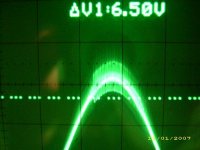
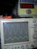
I got the same problem of noise at the top of the sinus wave with my proto
clock design @ 250kHz with IR2113 driver +2*IRFP4227
it occurs at 40Vpeak when driving 4 ohms
I'm using T106-2 core 47uH + 470nF MKP
rail voltage are +/- 80V
see pic...
could someone help ?
I got the same problem of noise at the top of the sinus wave with my proto
clock design @ 250kHz with IR2113 driver +2*IRFP4227
it occurs at 40Vpeak when driving 4 ohms
I'm using T106-2 core 47uH + 470nF MKP
rail voltage are +/- 80V
see pic...
could someone help ?
Attachments
Hi
I think that fredos said that you have to use big upper capacitance and lower too, but most important is as he wrote
And there is something that you gave ground plane under inductor, wich will increase winding capacitance and eliminate ringing.
I hope that this is right
I think that fredos said that you have to use big upper capacitance and lower too, but most important is as he wrote
0.47uF is cap that is connecteb between +V and -V as close to fets as possible.good 0.47uF 250V MKT will cure all ringing you have on your squared wave! Some 0.1uF ceramic with 4.7 ohms resistor to ground help a lot too...
And there is something that you gave ground plane under inductor, wich will increase winding capacitance and eliminate ringing.
I hope that this is right
Hi,
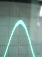
I took some shots of the waveform yesterday and, after some measurements, I notice that the problem has to do with the layout and absence of some decoupling caps, like Fredos said.
After some wiring mods the ringing was reduced and the amp easily swings more than 90vpp at 8ohms.
At this weekend I wil improve the wiring and will put some decoupling caps. after that I will try o achieve near full rail swing.
for an old analog audio guy its a very funny challenge to put this amp to work...
Tks all
Attachments
Hi
Looks good. What is your supply voltage? If you don't get good decoupling cap, buy one that has high voltage, ie. 630v. What happens if you go more than 90Vpp?
Looks good. What is your supply voltage? If you don't get good decoupling cap, buy one that has high voltage, ie. 630v. What happens if you go more than 90Vpp?
Luka,
The power supply voltage is 70V regulated in half bridge SMPS.
It´s able to put out more than 90vpp, but I prefer rewire and decouple the circuit before stress it.
by the way, actually I just forgot to glue the output coupled inductor of the power supply and the buzz of it when the current raises at 1kHz is awful. I will test more excursion after gluing that too...
best regards
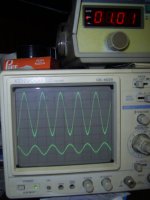
Here is other picture of it working with 35vdc at 1kHz. No problems and a clean waveform.
The power supply voltage is 70V regulated in half bridge SMPS.
It´s able to put out more than 90vpp, but I prefer rewire and decouple the circuit before stress it.
by the way, actually I just forgot to glue the output coupled inductor of the power supply and the buzz of it when the current raises at 1kHz is awful. I will test more excursion after gluing that too...
best regards
Here is other picture of it working with 35vdc at 1kHz. No problems and a clean waveform.
Attachments
Hi
Looks great, could you send me more info on smps and pic if you have them. Did you synchronize it with amp?
Looks great, could you send me more info on smps and pic if you have them. Did you synchronize it with amp?
I will take more shots and put them here.
The power supply is a half-bridge design using a SG3525 controller at 65kHz and 4 irfp450 feeding a toroidal transformer. It´s not syncronized.
I designed it to supply aprox. 1.5kW at output, but it was my first off-line design and for sure there is room for some improvement. I´m planning use a PFC stage in order to reduce the bulk capacitors at input, a real PITA to reduce the dimensions of the power supply at these levels of power.
The sum of power supply ripple and the amp ripple at voltage buses is really a mess...I´m planning to clean it too. I don´t know how, yet...
Below is the picture of the waveform at 20kHz 35vdc. 10v/division at output.
Best regards,
Attachments
- Status
- Not open for further replies.
- Home
- Amplifiers
- Class D
- Philips UCD application note