 pain
pain From the post here, I read that Bruno Putzeys himself even makes 5 or 6 pcb's before get 1 that works. Lets calculate. I don't use SMD. I just learn about classD. How many PCB designs will I have to toss away? 😀
lumanauw said:I read that Bruno Putzeys himself even makes 5 or 6 pcb's before get 1 that works.
I'm sure that's how many it takes before he gets one that works up to his standards, not just working in general 🙂
lumanauw said:From the post here, I read that Bruno Putzeys himself even makes 5 or 6 pcb's before get 1 that works. Lets calculate. I don't use SMD. I just learn about classD. How many PCB designs will I have to toss away? 😀
I'm like you - I'm not using SMD at the moment. Just about to try my 2nd prototype with through hole -- I've added OVP, OCP and differential input. I'm also not trying for more than about 75W from a +/- 28 V rail.
I agree with the comments that suggest trying lower power amplifiers before trying to build a big one - makes sense from a smoke point of view! 🙂
I found the best way to compare to the 'real thing' was to buy a UCD180, and compare it to my results, by using the same PSU, load etc... ---- not quite as good yet, but hopefully getting closer!
what is my problem?
I realize the schematic on board but I have a problem
I'm using MSPA92/42 and NTY100N10G, and +30/-30V
this is the wave with no load (50hz)
http://img267.imageshack.us/img267/9928/pict0003sf6.jpg
and I test with 6 ohm load the wave does not look like a sinus.
I realize the schematic on board but I have a problem
I'm using MSPA92/42 and NTY100N10G, and +30/-30V
this is the wave with no load (50hz)
http://img267.imageshack.us/img267/9928/pict0003sf6.jpg
and I test with 6 ohm load the wave does not look like a sinus.
I just bought a EE ferrite core. Something is strange. The ferrite has no gap. But when I wound the wire (0.7mm magnet wire), it takes 25 turns to get 30uH. This is above the suggested turns about 10-15turns.
Without gapping, it already takes quite some turns.
Do I still have to gap the core (grinding the center ferrite)?
Or is it OK for me to use it without gap? The size is about RM10 size.
Without gapping, it already takes quite some turns.
Do I still have to gap the core (grinding the center ferrite)?
Or is it OK for me to use it without gap? The size is about RM10 size.
The permeability of your core is lower if it takes more turns to get the same inductance. Gapping it will require you to use even more turns to get 30uH.
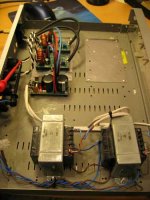
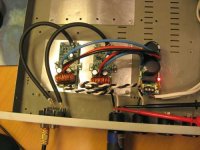
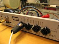
Time to try out my mini UcD in stereo on my main speaker setup.
I fitted the smal amps into an old DVD player casing ..... thee will be room enough for two more amps (will try out the amp running hysteresis mode).
Well I guess it should have been obvious, that it wouldn't beat my main amp (LC Audio "The end" with ULC input circuit, dual mono 180W out, 2 x 800VA + 4 x 22.000 uF RIFA)
Anyway I was almost thinking that it being a UcD it could beat anything🙄
Well it plays quite well. The bass is not as "deep" and does not have the same weight as the LC. The mid and high is quite distinct but very clear. The feeling of space and room is good, but not as relaxed, and well defined as on the LC.
But there was a problem with a high pitched tone being present all the time.
Think I've heard this before, when trying to put two amps in one case. As I recall it should help moungint the two amps as close together as possible .... but that was what I thought I hade already done.
Would it help syncronising the amps??
And hould bould that be done as easy as possible??
IT also have some 100 Hz "noise" .... gues it comes directly from the PSU.

I fitted the smal amps into an old DVD player casing
..... thee will be room enough for two more amps (will try out the amp running hysteresis mode).Well I guess it should have been obvious, that it wouldn't beat my main amp (LC Audio "The end" with ULC input circuit, dual mono 180W out, 2 x 800VA + 4 x 22.000 uF RIFA)
Anyway I was almost thinking that it being a UcD it could beat anything🙄
Well it plays quite well. The bass is not as "deep" and does not have the same weight as the LC. The mid and high is quite distinct but very clear. The feeling of space and room is good, but not as relaxed, and well defined as on the LC.
But there was a problem with a high pitched tone being present all the time.
Think I've heard this before, when trying to put two amps in one case. As I recall it should help moungint the two amps as close together as possible .... but that was what I thought I hade already done.
Would it help syncronising the amps??
And hould bould that be done as easy as possible??
IT also have some 100 Hz "noise" .... gues it comes directly from the PSU.
Attachments
Baldin said:But there was a problem with a high pitched tone being present all the time.
Think I've heard this before, when trying to put two amps in one case. As I recall it should help moungint the two amps as close together as possible .... but that was what I thought I hade already done.
Would it help syncronising the amps??
And hould bould that be done as easy as possible??
IT also have some 100 Hz "noise" .... gues it comes directly from the PSU.
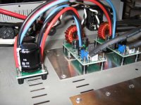
Hi Baldin. Does the high pitched noise go away if you only have one module powered? If so, the two modules are definitely interacting. It may help to physically space them farther apart.
Reloacte the rectifier side of the power supply board as far away from the module wiring as possible. That should help reduce the 100Hz noise a bit. Also try twisting the power supply wiring together for each module if possible.
I found a RM core, but the material is N27.
From a quick search on the net, this material is made by Siemens, and intended for power transformer below 100khz.
Is this RM core (N27) can be used for UCD output filter (with fosc near 500khz)?
From a quick search on the net, this material is made by Siemens, and intended for power transformer below 100khz.
Is this RM core (N27) can be used for UCD output filter (with fosc near 500khz)?
Has anybody experience this? When the mosfet's heatsink is attached to the case (=grounded), the residual output get distorted (sinusoidal becomes wrecked)?
How to counter this? The heatsink needs to be grounded, how to advoid this? I think this is because the low side Drain actually=full swing, and when this transistor gets grounded, it forms a capacitor between transistor's base metal plate (=full swing) and heatsink (=ground).
Is this why the real UCD uses plastic mosfets?
You should isolate the Fets from the heatsink by using appropriate TO220 insulating heat transfer material. Otherwise you would have a short from the supply rails to ground every time a fet switches ON.
My apology: Mounting the top fet directly to the heatsink (ground in your case) will short the positive rail to ground. Also, when the bottom fet switches on, you will be shorting the negative rail to ground. Use thermal insulating material.
Hi, Stephano,
I've used insulation mica and goop. The effect is very obvious. Do you also see this in your UCD?
I've used insulation mica and goop. The effect is very obvious. Do you also see this in your UCD?
- Status
- Not open for further replies.
- Home
- Amplifiers
- Class D
- Philips UCD application note