lumanauw said:Hi, Fumac,
I just experimented with my UCD-clone board. Before the worst mosfet is IRF540N. When I play the amp loud it only takes 1 second for the mosfet to blow.
I played with the gate resistors. Now I managed to make IRF540N not blown away with continious high level music, with Rg=220ohm. This is strange to me, the original Philips note uses only 22ohm for Rg. For IRF540N it has to be 220ohm, 10x the original value.
Fumac, is it OK to use 220ohm gate resistor?
But this comes with some expenses. First, the residual becomes 1V5 (p-p). Second, the gate drive (upper and lower mosfet Vgs) becomes triangle, not even close to square. But it survives for loud music now.
I guess IRF540N is not good for this cct. Using 220ohm Rg is actually slows down the turn-on. But in this case it is needed because the body diode of IRF540N is not good, slow (big trr), and have large Qrr. Using Rg=220ohm actually tries to minimize the cross-conduction, but sacrificing the dead time=worse THD.
The "chirping" bird sound is still there, I guess this is another problem with my board.
Fumac, what is the purpose of R24-C9, R23-C10 snubber? I change to 1nF+10ohm, it effects very little on the spikes on square edges.
Is there any other trick to remove the spikes on the square edges?
i have told u
that the ponit of ur project is the pcb.
the pcb make ur project to worst station
and i have told u that u can change the R of G, is just a way to make it work ok, but not work perfect!
220R is too large to make the THD LOWEST
this can let u know ur problom is the PCB
IRF540N i can driver it in 800KHZ work well
lumanauw,
what circuit are you using?? still from the philips app note?
if so, check your board.. even with THOSE widely spaced, it SHOULD work if there is no error....
what circuit are you using?? still from the philips app note?
if so, check your board.. even with THOSE widely spaced, it SHOULD work if there is no error....
Hi, RX5,
The schematic is ClassDfromRu's version 2.5.
Well....I'm not too disapointed that my UCD-clone is not working properly, for now, because it MAKES me learn alot 😀 There are many things learned in this single project, that is not obvious in analog amp DIY process.
I think every amp DIYer's should built this UCD-clone for once, it will make (no, not make, but FORCE) him to be a better DIY'er 😀
Ah I see.... anyway, a nice tip for you... just use +/-18V @1A.. and drive it to full volume.. if it over HEATS,, then something is REALLY wrong.... at those voltage levels, MOSFETS wont get hot.... stop using higher power PS for testing, it REALLY kills mosfets.. 🙂
lumanauw said:Do you know what is the mosfet type used in :
-UCD180
ST Micro's P14NF12FP
lumanauw
Yes R24-C9 and R23-C10 are snubbers. These will help reducing the ringing on the mosfets, but in order to be effective these of course needs to be very close to the mosfets.
A gate resistor of 220 ohm just seems really wrong ..... that is really not the real solution!
In my UcD I actually skipped the gate resistors (R19/R20 in the app note).
If you have cross conduction you should chose a higher value for R9 in the app note. At less than +- 25VDC the mosfets should not get moren than just warm .... not at all hot. Mine runs totally without heat sink on +-25VCD at 250 kHz. And as fumac says IRF540Ns are quite ok for a small UcD amp. (I'm using IRF640)
What frequency are you running at?
Did you try to move / turn the coil?? ....... please try it for me 😉
Making a compact layout will always help. I have found that with long leads and traces a class d amp tends to be noisy (not a single tone but broad banded). Compact designs will simply create less EMI and will also pickup less from other parts of the circuit (like from the high current rails).
But I'm not so sure that this is what causes your amp to blow.
In my amp the rails are routed directly under the gate drivers .... with no problem!
As RX5 says, try to go through the whole construction to see whether you have made some mistake somewhere, wrong component values, wrong connections etc.
Do you use the same component values as classd_fromru in the whole circuit??
lumanauw,
#1>>>... use +/-18V @1A..... play amp at full volume(if you want).. monitor mosfet.. it should NOT get hot... if it does, PLAY with the DEADTIME resistor.. (I wont tell the BEST value, IT will take the fun out of it 😀 experiment)
If mosfet/s do NOT get hot, see if your PS(trasnsformer) GETS hot also...changces are , it would NOT... proper adjustment (or selection) of deadtime resistor will eliminate cross-cunduction of the mosfet/s...
#2 does your output coil HEAT UP or some signs of it?? (at +/-18V 1A)
if you have done as per above, and still heats, then its time to review your work... stick to the actual components used ... later on you will know what part/s are involved in what.....
THIS is WHAT I have done -before- with my diy UCD.... take it up slowly and progress... I was in a hurry too, used +/-45V @ 8A as PS... man, even a little ERROR would quickly destroy my MOSFETs.. I also used IRF540N for my testing.. works OK.. but not the BEST.. IM using something else now.. much faster than the 540.... 😀 research for best mosfet/s.. I know I have posted an XLS here somewhere regarding what mosfets to use... up to you.....
Hi, Baldin,
I put cables on inductor, and move around the PCB. It has effect. While hovering in the air, in certain places it changes the magnitude of Vp-p residual seen on scope. The position of inductor (vertical/horisontal) while hovering also have effect.
This is getting more and more confusing.... 😀
I put cables on inductor, and move around the PCB. It has effect. While hovering in the air, in certain places it changes the magnitude of Vp-p residual seen on scope. The position of inductor (vertical/horisontal) while hovering also have effect.
This is getting more and more confusing.... 😀
Attachments
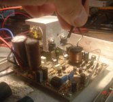
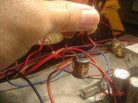
when the inductor is passing near supply rail cables (especially the +rail cable), the "chirping" bird sound becomes louder.
I guess this "bird" sound problem actually comes from layout/pcb problem.
Today I hear the amp again. 220ohm Rg = bad sound 😀
I have to fix the problem of this.
Fumac, is it possible that if I fix the PCB, I can use 10-22ohm Rg without blowing the mosfets in loud volume?
I guess this "bird" sound problem actually comes from layout/pcb problem.
Today I hear the amp again. 220ohm Rg = bad sound 😀
I have to fix the problem of this.
Fumac, is it possible that if I fix the PCB, I can use 10-22ohm Rg without blowing the mosfets in loud volume?
Attachments
Hi, RX5,
Where is it?
I know I have posted an XLS here somewhere regarding what mosfets to use... up to you.....
Where is it?
lumanauw said:Hi, RX5,
Where is it?
do a search on MY thread ...

youl find it there...
Hi, Fumac,
One more question. You use toroidal inductor. The windings are exposed, compared if you use sealed windings like RM cores.
Using toroidal doesn't give you problem ? If you don't, I will continue to use barbel core.
One more question. You use toroidal inductor. The windings are exposed, compared if you use sealed windings like RM cores.
Using toroidal doesn't give you problem ? If you don't, I will continue to use barbel core.
lumanauw said:Hi, Fumac,
One more question. You use toroidal inductor. The windings are exposed, compared if you use sealed windings like RM cores.
Using toroidal doesn't give you problem ? If you don't, I will continue to use barbel core.
i have buy 3,000 toroidal inductors,
have no problom on my board,
not heat on high power(200WRMS),good sound,low dis
lumanauw
Don't use your drum core
There is a huge difference in toroids and drums, a Toroid will contain the most of the field inside the core ("running around" in the core). A drum will radiate a lot of energy at both ends!!!
You have now seen how it affects the workings of the amp shifting the coil around. Start by changing to a toroid (e.g. Micrometals material #2 is really good for such application ..... dont just take whatever you can find😉)
It this doesen't help enough, you will have to do a new more compact PCB.
Hi, Baldin,
In your view, which is better. In here I can buy RM ferrite core (RM10-RM14) also toroidal of MPP and toroidal of KoolMu.
Between these 3, which one is the best material?
Which one is the best shape (that contained field the best)?
In your view, which is better. In here I can buy RM ferrite core (RM10-RM14) also toroidal of MPP and toroidal of KoolMu.
Between these 3, which one is the best material?
Which one is the best shape (that contained field the best)?
The RM cores here is not gapped yet.
How to make gap? By grinding to metalshop? How many mm is the gap? Inside or outside gap?
How to make gap? By grinding to metalshop? How many mm is the gap? Inside or outside gap?
Can't you locally get RM10 cores with a pre-made gap in the centre leg? Standard AL values for gapped cores are from about 60nH/turn^2 up to about 250nH/turn^2.
You can simply add a couple of pieces of paper or mylar film in the outer legs to act as spacers, but because this obviously gaps the outer as well as the inner, so there will be some external flux leakage.
You can simply add a couple of pieces of paper or mylar film in the outer legs to act as spacers, but because this obviously gaps the outer as well as the inner, so there will be some external flux leakage.
Yes, I saw LC's inductor is like that. Somewhere here, he mentioned that the spacing is 3mm for both inner leg and outter leg. But this introduce flux leaking?
I saw standard UCD400 picture, from outside the RM core is not gapped. Maybe the gap is only on inside core. But how many mm?
I saw standard UCD400 picture, from outside the RM core is not gapped. Maybe the gap is only on inside core. But how many mm?
- Status
- Not open for further replies.
- Home
- Amplifiers
- Class D
- Philips UCD application note