Re: Re: Re: Re: Re: Re: This may work ........
Hi.
It may be necessary to add a regulator to ,say, 125V to reduce off load voltage and voltage droop in use.
Andy
JeroenR said:
Yep, That's the one.
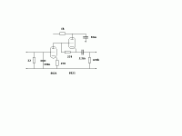
I used 47mF/160V caps as I was expecting 100V, not 150. Bit tight this way but at least it keeps the supply small. The red wire is the V-out. It is slightly boxed (alu) because it is close to outputs and the decoder/servo boards.
The decoder board is now empty where the opamps etc were. I hope to have just enough space for the tubes, caps and more caps...... and let's not forget the 6.3V supply.
Hi.
It may be necessary to add a regulator to ,say, 125V to reduce off load voltage and voltage droop in use.
Andy
Re: Re: Re: Re: Re: Re: Re: This may work ........
Why do you think that is necessary to add the regulator? Not enough head-room? I expect the tube circuit to draw about 1W (two time about 5mA at 100V) max.
Would someting like a 24reg and 100V zeners do the trick? But would that not require extra caps (space again)?
poynton said:
Hi.
It may be necessary to add a regulator to ,say, 125V to reduce off load voltage and voltage droop in use.
Andy
Why do you think that is necessary to add the regulator? Not enough head-room? I expect the tube circuit to draw about 1W (two time about 5mA at 100V) max.
Would someting like a 24reg and 100V zeners do the trick? But would that not require extra caps (space again)?
Re: Re: Re: Re: Re: Re: Re: Re: This may work ........
Exactly what I had in mind. The extra caps do not need to be huge - 47uF again
JeroenR said:
Why do you think that is necessary to add the regulator? Not enough head-room? I expect the tube circuit to draw about 1W (two time about 5mA at 100V) max.
Would someting like a 24reg and 100V zeners do the trick? But would that not require extra caps (space again)?
Exactly what I had in mind. The extra caps do not need to be huge - 47uF again
Re: Re: Re: Re: Re: Re: Re: Re: Re: This may work ........
Could I put a dummy load on the supply to simulate the power consumption and so see what voltage drop I can expect before I install the reg? I expect the tube-circuit will draw somewhere between 5 and 10mA per channel so perhaps a 20Kohm/5W to see what happens? Or will this do bang again?
I'm asking because I'm afraid that if I set the output to high (150V) then there will be not enough "room" for the reg and when I set the output too low (at 100V) there will be too much dissipation in the reg.
So perhaps the question is : how do I find out what the best value for the zener is?
Thanks,
Jeroen
poynton said:
Exactly what I had in mind. The extra caps do not need to be huge - 47uF again
Could I put a dummy load on the supply to simulate the power consumption and so see what voltage drop I can expect before I install the reg? I expect the tube-circuit will draw somewhere between 5 and 10mA per channel so perhaps a 20Kohm/5W to see what happens? Or will this do bang again?
I'm asking because I'm afraid that if I set the output to high (150V) then there will be not enough "room" for the reg and when I set the output too low (at 100V) there will be too much dissipation in the reg.
So perhaps the question is : how do I find out what the best value for the zener is?
Thanks,
Jeroen
Try without the reg. to start.
It may be necessary to revise the power supply if too much hum.
Andy
It may be necessary to revise the power supply if too much hum.
Andy
poynton said:Try without the reg. to start.
It may be necessary to revise the power supply if too much hum.
Andy
I certainly will try this weekend. After the supply there will be a resitor and one more cap directly connected to the plate of the top tube so perhaps if I take a good cap, add a choke somewhere.....
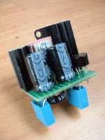
I'll get back again with diagram and photo's later.🙂
Thanks,
Jeroen
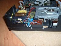
JeroenR said:Deforrestation........ room for the tubes.
where is the heater Tx?
Andy
poynton said:
where is the heater Tx?
Andy
It's the black block in front of the cdm.
JeroenR said:
It's the black block in front of the cdm.
Good luck !
Do we call the fire brigade now or later ?
Andy
poynton said:
Good luck !
Do we call the fire brigade now or later ?
Andy
Uhhh... why?
poynton said:
Good luck !
Do we call the fire brigade now or later ?
Andy
Come on Andy, the suspense is killing me.🙂
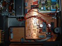
Are the tracks too close? Shouldn't I put the tx's parallel?
JeroenR said:
Come on Andy, the suspense is killing me.🙂
Are the tracks too close? Shouldn't I put the tx's parallel?
It was a Joke !
😀
poynton said:
It was a Joke !
😀
You ....... 😀
New to this as I am I really spent some time thinking and rethinking what I did wrong.
And... it works. I can regulate with the pot to 6.3V. Still have to try with load though.
My 104 doesn't like CD-R`s, no proplems with orig. disc's. Have cleaned the lens, blackened the transport chassis inner surface. Any more hints on improving this? Seems it doesn't improve when burning slower, have tried 2 different recorders and various disc brands... It's odd, it's playing all orig. discs, no matter how dirty and scratchy they are... Thanks guy's!
Thanks Bernhard, I've already tried this. I think the problem is created by those old Electrolytics, as there's a lot of hum on the Power supply rails (~200mVpp).
It doesn't even recognize the cd-r's - no TOC redout....
Will replace them and try it again.
The eye pattern looks very blurred, might originate to the noisy power supply ...?
Markus
It doesn't even recognize the cd-r's - no TOC redout....
Will replace them and try it again.
The eye pattern looks very blurred, might originate to the noisy power supply ...?
Markus
- Home
- Source & Line
- Digital Source
- Philips CD104 tweaks