Hi Ed!
I am sure everyone would like to hear your Phidac comparison to DDDacs,
especially since they are reportedly better sounding than Chord Qutest!
That would be one of the first (indirect, but still) comparisons to established good brands.
Could you post a couple more pictures? I get that the Wima are Boxed Red and they are for DC protection? Did you try first without them? What are the metal caps?
Hi,
First thanks to Richard for creating this dac kit.
Shipping was fast and packaging excellent.
I have started soldering and now values are looking better.
I got carried away, forgot to breathe, and managed to solder U2 180 degrees wrong, not recommended.
Now i have these values (Before filter insert)
Step 1
TP1: 6.9
TP2: 10.0
TP3: 5.0
TP4: 2.5
TP9: 12.4
TP10: 11.2
Step 2
TP5: 10.0
TP6: 10.0
TP7: 3.7
TP8: 3.7
Values after filter insert:
TP5: 5.8
TP6: 5.8
TP7: 8.0
TP8: 8.0
Still no music.
Any ideas how to progress?
Seb
TP1 etc values all look fine.
Step 2 (no filter) TP5-8 values are checking the biassing current sources output the correct current - this also looks fine.
Assuming that music is playing for the TP5-8 values with filter they are indicative of some problem with the DAC chips - either on the input or output side.
Each chip outputs an offset current at 'digital zero' and this is compensated for by the aforementioned current sources Q15 and Q25. When the two are in balance the TP5-8 values will be the same as TP1, i.e. 6.9V. Since TP5 is about 1V too low this indicates the DACs are putting out too much current. This couldn't happen by disconnecting the outputs (which would give too little) so it tends to indicate the data the DACs are receiving is corrupted somehow.
Of course it could be that you made those measurements with no music playing in which case the DAC's outputs will be random.
I have another question - you mentioned in email that you found 1N4001 had been put in backwards - did you discover this before you soldered in the DAC chips or after? If after its quite possible the DAC chips got damaged through over-voltage.
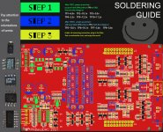
Updated graphic for how to solder your DecaDAC
In the light of a couple of builders getting some parts' polarities incorrect we've modified the build instructions to show the correct orientation of semis more explicitly. Hopefully to head off any future instances of this 🙂
In the light of a couple of builders getting some parts' polarities incorrect we've modified the build instructions to show the correct orientation of semis more explicitly. Hopefully to head off any future instances of this 🙂
Attachments
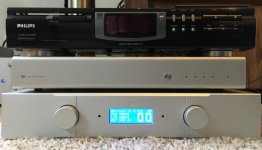
For several weeks now, my My PhiDAC hex has been working in this reused Philips CD Player enclosure.
I think I have to test with 3rd order filter also and purchase another filter from abraxalito. Initially I have ordered 2 kits incl. 7th order filters instead of different filters to play with.
The PhiDAC hex offers a wide sound stage but I am not 100% satisfied with the tonallity. Pre ringing of filter or phase shift caused by filter steep?
Attachments

I'm curious to learn what in particular is amiss about the tonality? There can't be any pre-ringing as the filter's causal (being analog) but there certainly is a fair amount of phase shift (and hence ringing) at the highest frequencies.
I see your sample rate shows as 48kHz - there will be some HF lift at any sample rate above 44.1kHz. I wouldn't expect it to be enough to be audible at 48k though.
I see your sample rate shows as 48kHz - there will be some HF lift at any sample rate above 44.1kHz. I wouldn't expect it to be enough to be audible at 48k though.
Yes of course there can not be any pre ringing, wrong translation.
Will try the 3rd order filter and find out which one matches better.
Will try the 3rd order filter and find out which one matches better.
dddac/phidecadac
Hi Darksound!
About comparision between DDDac and Phideca?
It's to soon for me to tell some reasonable things about this. The DDDac1794 i use for about I think eight years now, is a two deck build, with a buffer thought out by a diyaudio-member. Including two Tent shunt mods per deck and folowed by an early fifo-reclocker (IanCanada) and than two 600/600 Ohm transformers per channell.
A rather complicated creature but sounding beautiful. (without getting in details)
Comparing apples and oranges I am afraid
But the Phideca blows it's trumpet .like an adult!
Sounding very nice already with a wallwart 15 Volt and a simple C-Media Usb to i2s board. after I changed the Usb converter with the one I use for my DDDac, the 'Luckit' with nice clocks, together with a Salas shunt, bettered
the presentation a little by bringing a bit more rest in the image, a little less forward. Just a little.
Is it worth getting one for so little money? I asure it is. It is playing 24 hours
constantly for the last two weeks, making just very balanced music and I can live with it. (my music preference is acoustical recordings among several I made myself in the past fourty years of choruses and classical concerts. Mostly in beautiful churches.
Timbre of voices and instruments is very precise including the fantastic reverberation of those places!
I like this dac!
BTW: The caps are indeed needed for getting rid of about 7V DC. The wima's do not sound wrong, but it is fun playing with different makes, or combinations of those.
Hi Ed!
I am sure everyone would like to hear your Phidac comparison to DDDacs,
especially since they are reportedly better sounding than Chord Qutest!
That would be one of the first (indirect, but still) comparisons to established good brands.
Could you post a couple more pictures? I get that the Wima are Boxed Red and they are for DC protection? Did you try first without them? What are the metal caps?
Hi Darksound!
About comparision between DDDac and Phideca?
It's to soon for me to tell some reasonable things about this. The DDDac1794 i use for about I think eight years now, is a two deck build, with a buffer thought out by a diyaudio-member. Including two Tent shunt mods per deck and folowed by an early fifo-reclocker (IanCanada) and than two 600/600 Ohm transformers per channell.
A rather complicated creature but sounding beautiful. (without getting in details)
Comparing apples and oranges I am afraid
But the Phideca blows it's trumpet .like an adult!
Sounding very nice already with a wallwart 15 Volt and a simple C-Media Usb to i2s board. after I changed the Usb converter with the one I use for my DDDac, the 'Luckit' with nice clocks, together with a Salas shunt, bettered
the presentation a little by bringing a bit more rest in the image, a little less forward. Just a little.
Is it worth getting one for so little money? I asure it is. It is playing 24 hours
constantly for the last two weeks, making just very balanced music and I can live with it. (my music preference is acoustical recordings among several I made myself in the past fourty years of choruses and classical concerts. Mostly in beautiful churches.
Timbre of voices and instruments is very precise including the fantastic reverberation of those places!
I like this dac!
BTW: The caps are indeed needed for getting rid of about 7V DC. The wima's do not sound wrong, but it is fun playing with different makes, or combinations of those.

Hi everyone! Just a silly question:
To connect the usb/I2s interface to the dac:
With wich pin do I have to connect the dac´s BCK pin?
To connect the usb/I2s interface to the dac:
With wich pin do I have to connect the dac´s BCK pin?
Richard.
The Phidac l built is one of the early one.
can you point me to any circuit updates please
Thank you
kp93300
The Phidac l built is one of the early one.
can you point me to any circuit updates please
Thank you
kp93300
The Deca DAC has replaced the PhiDAC hex, the most recently posted schematic is here : https://www.diyaudio.com/forums/digital-line-level/324933-lingdac-cost-effective-rbcd-multibit-dac-design-55.html#post6474684
While the I/V and filter circuits are almost identical to the 'hex' (ignoring opamp upgrades), the power supplies have changed substantially.
While the I/V and filter circuits are almost identical to the 'hex' (ignoring opamp upgrades), the power supplies have changed substantially.
Hi Richard!
I have completed the soldering, but I have no sound. Those are my voltages:
Wihtout filter:
TP1 6.93
TP2 10.02
TP3 5.06
TP4 2.50
TP9 12.49
TP10 11.24
TP5 10.05
TP6 10.08
TP7 3.66
TP8 3.67
With 3rd order filter
TP5 6,62
TP6 6,87
TP7 7,03
TP8 6,76
I have observed that when I put the filter on the measurements start at 6.7v and gradually increase. In about 3 or 4 minutes, the voltages are:
tp5 6.64v
tp6 7.02v
tp7 7.25v
tp8 7.05v
Do you know how could I solve it?
Thanks!
Last edited:
All those voltages seem fine to me. I'd check you have the I2S correctly connected to your source.
After making several beginner mistakes, and with the help of Richard (probably the most patient person in the world), I have gotten my Phideca Dac to work!
I encourage everyone who is in doubt to do so. If I could, anyone can do it. Richard's help, care, and support are exceptional. Tomorrow I am going to put the dac in a solid aluminum case and I will never touch the board again, haha.
Regarding the sound, after a brief listening, I can say that it sounds much better than my Khadas Tone Board. The sound is much more alive, with the 7th order filter I can hear details that I did not perceive before. It is as if the dac extracts more music. For now I am delighted.
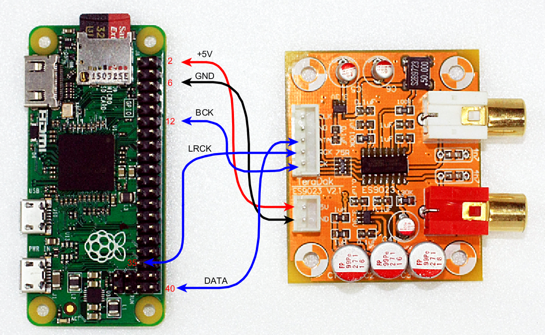
One question: to connect the dac directly to the gpio port of a Raspberry Pi 3b, would this scheme be valid?
I encourage everyone who is in doubt to do so. If I could, anyone can do it. Richard's help, care, and support are exceptional. Tomorrow I am going to put the dac in a solid aluminum case and I will never touch the board again, haha.
Regarding the sound, after a brief listening, I can say that it sounds much better than my Khadas Tone Board. The sound is much more alive, with the 7th order filter I can hear details that I did not perceive before. It is as if the dac extracts more music. For now I am delighted.
One question: to connect the dac directly to the gpio port of a Raspberry Pi 3b, would this scheme be valid?
Well done Carlos for persevering with your damaged DAC!
The connection to the RPi looks OK though no +5V wire will be needed by the Deca DAC. So just 4 wires.
The connection to the RPi looks OK though no +5V wire will be needed by the Deca DAC. So just 4 wires.
Hi Richard!
I've been reading about the influence of clocks on the sound of dacs. I use a Raspberry PI as a source, which is provided with clocks that are not 44.1 and 48 MHz divisors, so they could negatively affect the sound produced by the dac.
I have investigated about reclockers type Ian's Canada FIFO PI, Allo Kali reclocker or usb / I2S interfaces type AS318B
Ian asynchronous I2S and S/PDIF FIFO KIT group buy
Kali (i2s Reclocker)
Interfaz digital USB AS318B PCM1536 DSD1024, compatible con Amanero Italy XMOS a I2S|Conversor de digital a analogico| - AliExpress
In the case of using the Phideca Dac with a Raspberry pi, the use of one of these interfaces instead of a CM6631a type I2s usb interface
Would it make any noticeable improvement to the sound?
Hi Carlos - the first thing is the RPi has 'native' I2S output - that's dedicated hardware on the CPU chip to handle I2S. Its that route which gives rise to a very jittery clock as the CPU isn't running at an audio rate multiple. That dedicated I2S bus has its connections on the 40way header you show in post #315.
However if you use the RPi USB interface to drive the CM6631A card, then the clocks on the CM6631A card are providing the clock - assuming you take I2S from the USB card and not from the 40way header. This route gives low jitter clocks.
I am making the assumption here that CMedia have drivers for CM6631A under Linux. I don't know if that's the case.
Hello,
I use Raspberry pi => i2s to hdmi=>hdmi to i2s=>Ian canada isolator=>Kali=>decadac or pcm 1704 opa861.
The result is more definition, less noise analog and digital, no interference from Raspberry to dac.
Regards
Guglielmo
I use Raspberry pi => i2s to hdmi=>hdmi to i2s=>Ian canada isolator=>Kali=>decadac or pcm 1704 opa861.
The result is more definition, less noise analog and digital, no interference from Raspberry to dac.
Regards
Guglielmo
Have you ever tried or thought about using a higher cut off point for a NOS filter so as to minimise audibility of phase shift?
The downside is no complementary droop correction and virtually no suppression of at least the first image, but still nuking most of the RF in the signal passively, and as a small side bonus it wouldn't be limited to 44.1kHz (for high res or light OS).
Is it the first images that are the most problematic? It wouldn't be a very good reconstruction filter then, but after some recent experiences of adding LC filtering to power supply input I've started to wonder if RF isn't the bigger problem that these passive filters address.
With simple DAC filters there was a sweet spot for me, going too low there are sort of smearing effects and it is not correctable with EQ... I think this is phase shift?
The (maybe foolish) assumption that this is phase shift had put me off trying one of these filters (but also that there wasn't a NOS DAC that I liked enough to bother).
Seeing as light to virtually no filtering on NOS DACs doesn't sound that bad to me there is a chance this slightly different approach would be a worthy compromise.
- Home
- Vendor's Bazaar
- PhiDAC hex kits with pre-built filters