

George
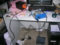
Very elaborate power supply.
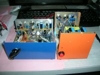
is it pc power supply casing ?
Can you comment on the sound .
Do you use Richard's TDA 8932 amp also ?
Very elaborate power supply.
is it pc power supply casing ?
Can you comment on the sound .
Do you use Richard's TDA 8932 amp also ?
Hi kp
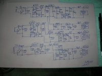
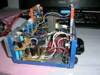
PSU is important, despite the on-board arrangement on all three boards.
The enclosures are actually the only peripheral -i.e. apart from the i2soverUSB, PhiDAC and headphone buffer boards- components I bought for this project. All the rest were in my drawers or in plastic bags on the floor or recicled from abandoned projects.
You won't ask an almost deaf guy commenting on sound.
I do some measurements, I will post in due time.
No, I haven't ordered Richard's carefully designed TDA 8932 amp.
George
DAC setup for my PC
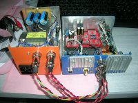
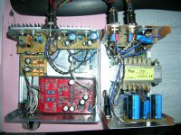
George - I see from your interesting photos that you're using the 3rd order filter in the PhiDAC. Did the 7th order ones not come together for you? Or did you listen to both and prefer the 3rd?
Hi Richard
The 7th order filter is too up and running . Both filter boards work OK.
As I am still in the basic testing phase-PSU trimming-rewiring, the smaller size of the 3rd order filter is of some benefit .
George
The 7th order filter is too up and running . Both filter boards work OK.
As I am still in the basic testing phase-PSU trimming-rewiring, the smaller size of the 3rd order filter is of some benefit .
George
Attachments
Nice FFT results - really low odd orders - well done abrax!
gpapag, can you measure also at high level, say just below 0.
And, can you do an IM and multitone (10?)?
//
gpapag, can you measure also at high level, say just below 0.
And, can you do an IM and multitone (10?)?
//
Last edited:
The image frequencies with the 3rd order filter are reduced more by the sinc function at 1kHz than by the filter. They're still the dominant spurs though. I take it the calculated THD number sums the true harmonics and ignores the images.
Part of TNT's wish list is here. (REW software)
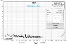
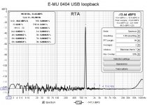
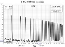
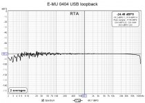
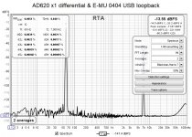
First this is the soundcard loopback test .
Input levels shown are the maximum just before the soundcard input circuit starts to distort.
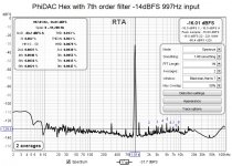
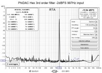
Single tone is 997Hz
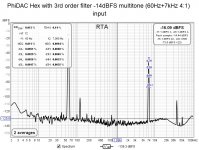
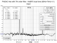
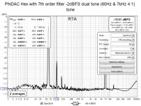
Dual tone is 60Hz & 7kHz 4:1
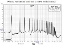
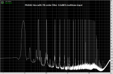
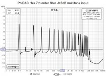
Multitone is 39 tones 8Hz to 96kHz, crest factor 12.3dB.
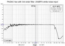
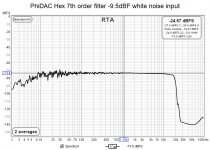
Noise is white random
George
First this is the soundcard loopback test .
Input levels shown are the maximum just before the soundcard input circuit starts to distort.
Single tone is 997Hz
Dual tone is 60Hz & 7kHz 4:1
Multitone is 39 tones 8Hz to 96kHz, crest factor 12.3dB.
Noise is white random
George
Attachments
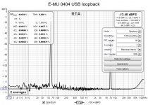
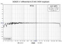
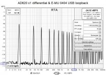
Next are the same tests conducted with the AD620 x1 gain instrumentation preamplifier in the loopback. I use it in differential mode so I probe the circuit with two probes avoiding to create extra ground loops.
George
George
Attachments

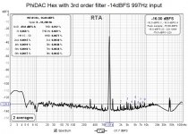
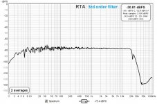
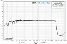
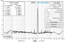
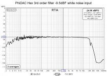
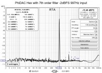
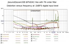
Last, PhiDAC Hex with 7rd order filter
Tests with higher levels of input signal will be done later, using a voltage divider at the input of the soundcard, so as the input level will be kept the same as with the tests above.
George
Tests with higher levels of input signal will be done later, using a voltage divider at the input of the soundcard, so as the input level will be kept the same as with the tests above.
George
Attachments


For to do the high level signal test, I had to check for the maximum undistorted output of the digital signal (REW software warns:"Signal is cliping at digital full scale"). These output levels are:
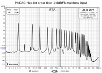
997Hz tone :-2dBFS
dual tone 60Hz & 7kHz 4:1 : -2dBFS
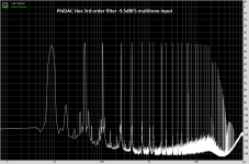
multitone: -9.5dBFS
white noise: -9.5dBFS
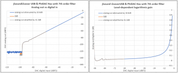
The probed DAC analog output is attenuated by an 100kOhm potentiometer downstream of the AD620 x1 differential preamplifier before it enters the input of the soundcard.
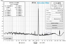
DAC with the 3rd order filter
George
997Hz tone :-2dBFS
dual tone 60Hz & 7kHz 4:1 : -2dBFS
multitone: -9.5dBFS
white noise: -9.5dBFS
The probed DAC analog output is attenuated by an 100kOhm potentiometer downstream of the AD620 x1 differential preamplifier before it enters the input of the soundcard.
DAC with the 3rd order filter
George
Attachments


 I bow for you gpapag! Impressive effort!
Some more measurements.
DAC with 7th order filter.
(spikes at 1st attachment are measurement glitch, there is no real distortion peaking)
George
DAC with 7th order filter.
(spikes at 1st attachment are measurement glitch, there is no real distortion peaking)
George
Attachments
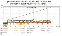
It measures good enough!!
The second measurement in the last post was an interesting one... level vs dist, don't think I saw that one before.
In the first one you say -2dbfs but chart says fundamental -15,6?
//
The second measurement in the last post was an interesting one... level vs dist, don't think I saw that one before.
In the first one you say -2dbfs but chart says fundamental -15,6?
//
Right.
Digital input level of DAC is at -2dBFS.
Analog output of DAC goes through an attenuator so the signal level at the analog input of the E-MU 0404 soundcard remains close to but below -13.44 dBFS for undistorted measurement (see post 131).
George
Digital input level of DAC is at -2dBFS.
Analog output of DAC goes through an attenuator so the signal level at the analog input of the E-MU 0404 soundcard remains close to but below -13.44 dBFS for undistorted measurement (see post 131).
George
- Home
- Vendor's Bazaar
- PhiDAC hex kits with pre-built filters