Don't know why the third thumbnail in the prior post is so big now. It wasn't the first day I posted.
Thanks to those who viewed.
Thanks to those who viewed.
Comments are of course welcomed.
Now 55th year as a bench oldtimer, ..Many of us have always known about the cathodyne deficiencies and really they are slight; below unity gain, dissimiliar noise and unequal output impedances esp at higher frequencies often dominated by next stage loading Cin; the latter often contributes to higher power amp thd at the top end freq.. The classic bathtub THD curve cannot all be blamed on the output transformer but with unequal driving signals it doesn't help.
I use the cathodyne at its best when feeding into high impedance diff driver stage; Williamson + GEC do it well in their KT66-15/30W amp stages which with self balancing common cathode diff drivers nicely camouflages any cathodyne's shortcomings.
IMO the cathodyne should really be modeled with a diff driver stage where minimalist but consistent input loading takes place. The result is what I would anticipate, symmetry couldn't be better. By sine wave observing (scoping) the common cathode connection on the diff driver one should see the f2 component which has local feedback with the grid resistors, that any mis-amplitude occurring is clearly visible and is automatically corrected at the driver anodes. One has to be content with one's lot, simplicity and couldn't ask for more !
Add global NFB; Viva, all is corrected. Anything wrong in that ?
rich
Rich, I agree with your "cathodyne at its best" and "with a diff driver stage where minimalist but consistent input loading takes place" comments.
That being said, I'm not arguing for or against its use in any particular situation. I'm just trying to straighten out some misconceptions presented in the past about the circuit's characteristics.
That being said, I'm not arguing for or against its use in any particular situation. I'm just trying to straighten out some misconceptions presented in the past about the circuit's characteristics.
The problems of the traditional “floating” Cathodyne Model are evident without invoking simulators or resorting to analyses based on Kirchhoff’s laws.
It’s obvious that the Model ignores the question of power supply rejection; to it, Cathodynes with 10mV and 10V B+ ripples are identical. Also ignored are the effects of the value of the (matched anode and cathode) loads – 10 kOhm circuits are indistinguishable from 10 ohm ones. Of course, bench tests easily reveal both types of differences.
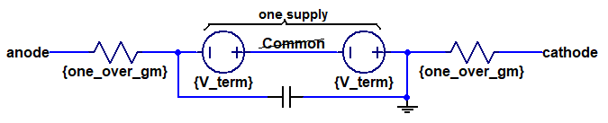
The Model is like a transformer winding. Each specifies a pair of terminal voltages with respect to that of a third terminal to which the pair is connected. For the winding, that terminal is its center tap; for the Model, it’s an imaginary “Common” terminal.
Just as with a transformer, without a ground connection, the Model cannot specify voltages with respect to ground. (As such, the Model befuddles simulators – see attached.) This is a real problem for a circuit whose purpose is to drive an output stage which is controlled by its ground-referenced grid voltages (its cathodes are typically AC-grounded), not by its inter-grid voltage difference (as specified by the Model.) As if that were not enough, in the absence of ground, there is no closed path through which high signal level output stage grid current can flow. An acceptable model must have connections to ground.
In summary, the Model disregards B+ supply noise, is insensitive to (matched pair anode and cathode) loading, does not specify the signals which control the output stage, and doesn’t support the flow of that stage’s grid current under high signal level conditions. A different model is required if these unfortunate deficiencies are to be addressed.
It’s obvious that the Model ignores the question of power supply rejection; to it, Cathodynes with 10mV and 10V B+ ripples are identical. Also ignored are the effects of the value of the (matched anode and cathode) loads – 10 kOhm circuits are indistinguishable from 10 ohm ones. Of course, bench tests easily reveal both types of differences.
The Model is like a transformer winding. Each specifies a pair of terminal voltages with respect to that of a third terminal to which the pair is connected. For the winding, that terminal is its center tap; for the Model, it’s an imaginary “Common” terminal.
Just as with a transformer, without a ground connection, the Model cannot specify voltages with respect to ground. (As such, the Model befuddles simulators – see attached.) This is a real problem for a circuit whose purpose is to drive an output stage which is controlled by its ground-referenced grid voltages (its cathodes are typically AC-grounded), not by its inter-grid voltage difference (as specified by the Model.) As if that were not enough, in the absence of ground, there is no closed path through which high signal level output stage grid current can flow. An acceptable model must have connections to ground.
In summary, the Model disregards B+ supply noise, is insensitive to (matched pair anode and cathode) loading, does not specify the signals which control the output stage, and doesn’t support the flow of that stage’s grid current under high signal level conditions. A different model is required if these unfortunate deficiencies are to be addressed.
Attachments
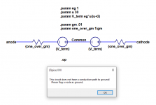
The thumbnail I provided was not my own Model; it was copied from a Linear Audio article by Stuart Yaniger and received a favorable review from Burkhard Vogel.
In general, I agree with your comments. Although I do not oppose combining the two supplies into one and eliminating "Common", neither do I see that it solves anything. And the ground you added to your thumbnail means that there is no signal at the cathode. Bench tests will show this to be a problem.
Without a valid connection to ground, your thumbnail addresses none of the problems I listed regarding the thumbnail I posted.
😕 The signal is on the cathode resistor, one side ground other side = cathode = signalAnd the ground you added to your thumbnail means that there is no signal at the cathode.

Mona
How does the signal get to the "other side" of the cathode resistor? I see no connection in your model to the cathode terminal.
Simulate?
Why?
Build a concertina splitter. Connect the splitter to the working output stage control grids (a working amp, preferably with any global negative feedback disabled).
Now, use two probes: 10X, 10Meg, about 5 to 15pf, and a 2 channel scope. Set the scope to AC couple on both channels.
Check that the probes and channels have both matched gain and matched frequency response by putting them both on a square wave, and observing the trace matching. Adjust the probe(s) compensation if it is needed.
Drive the splitter with a 1kHz sine wave. Connect the probes to the cathode and plate of the splitter. Check the phase and gain match.
You may choose to use the Invert function on one channel.
Drive the splitter with a 20kHz sine wave. Connect the probes to the cathode and plate of the splitter. Check the phase and gain match.
You may choose to use the Invert function on one channel.
(do not drive the splitter so hard that it has grid current; And be sure that the filament is powered by a floating supply (Very Low capacitance to ground). A 6V battery will work.
Now you will know what you get on your exact amp circuit.
No simulation software.
Report back to us with what you got, Please.
Occasionally measurements do not lie.
Last edited:
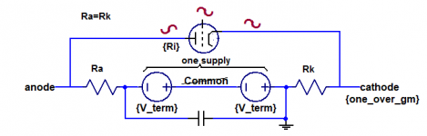
Like this ? 🙂How does the signal get to the "other side" of the cathode resistor? I see no connection in your model to the cathode terminal.
Mona
Attachments
The Model is a model of the triode - it is not an addition to the triode. It replaces the triode. You can either have the Model or you can have the triode. You cannot have both.
6A3sUMMER, let us hope and pray that we all know how to make measurements.
The whole point of my post was to discuss a fallacious model, not to argue that any model can replace measurements.
The whole point of my post was to discuss a fallacious model, not to argue that any model can replace measurements.
That is a very wierd model with 1/g on both sides and two voltage sources with no relation to Vg, and where is the Ri 😕.The Model is a model of the triode - it is not an addition to the triode. It replaces the triode. You can either have the Model or you can have the triode. You cannot have both.
Complete nonsens if you ask me.
Mona
To assemble a new circuit, it is highly desirable to have an understanding of the effects that components of various values will have on circuit performance. Guided by this, performance is confirmed by bench measurements. Without such an understanding, you could be modifying your circuit over and over, hoping to achieve the results you desire without ever knowing if it is even possible to do so.
6A3sUMMER might prefer to ignore the guidance afforded by models, but others will benefit by making use of the information they provide. A good model and a bench test: each has its place in the process of creating a new circuit.
The purpose of my earlier posts was to disclose the limitations and flaws of a certain popular model and point out that there is an alternative which corrects those problems and improves its accuracy.
Ketje, as I'm sure you've read, I am no fan of this model. But your Vg is the eg in the .param statement of what I posted. V_term, the voltage of each source, is set by another .param statement to be u eg / (u + 2), where u is the triode mu. In my view, the model makes some sense, but it still should be rejected for the reasons I've posted.
1. Except for drawing grid current, grid to plate capacitive current versus grid to cathode capacitance currents, and filament to cathode capacitive and filament to cathode leakage currents . . .
Then, the current change in the cathode circuit is exactly the same as the current change in the plate circuit.
2. That is true, no matter what the cathode impedance is versus what the plate impedance is (but only if you use identical cathode and plate resistors, identical coupling caps, and identical next stage grid resistances to ground).
The balance of the concertina is very very very good if you pay attention to # 1. and # 2. above.
Well, even given that, I still am not a fan of the concertina.
So I defend the concertina, but do not use the concertina.
1. and 2. - Agreed and never contested.
Surely there is no need to defend the Concertina from me, for I have never attacked it; I have simply challenged a model of it.
Surely there is no need to defend the Concertina from me, for I have never attacked it; I have simply challenged a model of it.
I will attach two pages from EW mag. about concertina, which give good explanation about
the rationale behind it, and add a few thoughts on the subject.
It is not the issue with (un)equal output impedances at anode and cathode - it is the issue
of the equal input impedances presented by the load - the PP active devices.
With tubes their input capacitances stay practically constant (with signal). ("Non-constancy"
is determined by the tube' distortion coefficient.)
It is obvious that the Conc. A-C current is determined by the action at the cathode, but
the anode current is equal to the cathode current, and since the R+C loads are also equal,
then both output voltages at A. and C. will also be sufficiently equal.
The interesting stuff comes with PP transistors, which have substantially non-linear capacitances.
When output power trans connected to the cathode will be, let's say, fully on, and it's capacitance
will be at max value, the opposite PP trans will be off and it's capac. will be at minimum, so R+C
presented by the loading transistors will be different. Then the current generated at cathode will
be equal at the anode, but the driving voltages generated at the gates/bases of the output PP
transistors will be unequal - always.
Obviously, PP with transistors will require different phase splitters.
Attachments
It's surprising how often we see misunderstandings about the Cathodyne/Concertina/Phase Splitter over the years, even from well-respected authors.
One general point of agreement is that if the parasitic capacitances of its triode are ignored, the voltages at the anode and cathode are equal in magnitude and opposite in phase as long as the loads on these two terminals are identical. This is a simple consequence of the fact that the anode and cathode currents are one and the same and produce this result when they pass through identical loads. It's wrong to claim that this somehow implies a specific relationship between the circuit’s ground-referenced anode and cathode impedances, Za and Zk. The assertion that they are identical and approximately 1/gm or 2/gm is easily debunked.
Consider a 12AU7 biased at 5mA and 100V. Its gm is approximately 1 / 500 ohms. This triode is at the heart of a circuit with 10kOhm loads and a 200V B+ supply. Now, there‘s no such thing as a noiseless B+ supply. And since the Concertina is linear, regardless of the magnitude of the B+ noise, the ratio of the magnitude of the portion of the B+ noise at any other point in the circuit to that at the B+ terminal itself is constant. To make it easy to determine this ratio in a bench test, a poorly filtered and rectified B+ with a 100mV peak-to-peak ripple can be employed. If the ground-referenced anode impedance were approximately 1/gm, then the ratio of the noises at the anode to that at B+ would be given by the expression of a simple resistive voltage divider: 500 / ( 500 + 10000 ), or about .05. Instead, we measure a ratio of roughly .95. This can happen only if the impedance looking into the anode is about z = 200kOhms rather than something anywhere near 1/gm. The circuit’s anode impedance would then be z || 10kOhms, slightly less than 10kOhms.
I’d be happy to present a derivation of Za and Zk. But first let’s see if we can get an acknowledgement that these bench test results refute the 1/gm anode impedance claim.
In the meantime, take a look at the classic Albert Priesman and George E. Jones papers from the 1950’s. These guys got it right, long before the misperceptions started to appear:
https://www.aikenamps.com/images/Documents/cathodyne.pdf equations (1) and (2)
https://www.worldradiohistory.com/Archive-All-Audio/Archive-Audio/50s/Audio-1951-Dec.pdf p, 16, text and equations, 1st column.

If the split is perfect, then the amplitudes would have to be the same, since that's a part of the perfection.Has anyone ever built a concertina phase splitter and have the signal be perfectly split but they differed in amplitude?
- Home
- Amplifiers
- Tubes / Valves
- phase splitter issue