I only had a few minutes to work on the amp last night. I tried switching the silpads to mica and grease for the drivers (outputs are removed) and the oscillation improved a small amount, but is still present.
I did a bunch of testing tonight, all was done with only the drivers in and no outputs. One change I made that greatly reduced the amount of background noise "hash" riding on the L channel signal was adding Wima MKP .01uF bypass caps to the -/+ rails on the control pcb. I put them across the traces down low on the board where the Gnd, + & - signal traces run side by side. After adding these caps the L ch output is now nearly as clean as the R channel. I still see a slightly higher amount of higher freq ripple riding on the sine wave for the L ch if I get down to the .1V range on the scope. This ripple is probably 1mhz in freq and appears to be the same intensity throughout the whole 360 degree cycle. I do not see this same high freq ripple on the R ch. The level of this ripple remains the same regrdless of the input signal level. So if I bring the amp output up to say > 2Vpp this ripple is imperceptible, but my OCD says the channels don't match and it drives me nutzzzz.
I'll probably try installing an output transistor in each bank tomorrow night and see how the signal looks when running through the outputs.
I'll probably try installing an output transistor in each bank tomorrow night and see how the signal looks when running through the outputs.
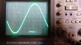
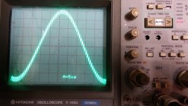
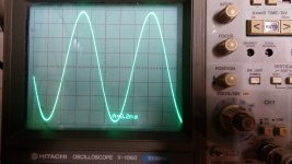
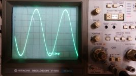
Took some pictures of the output waveforms, this is once again with the drivers only, no outputs. I included both L and R signals for comparison. One is about .8Vpp (20Khz sine) and the other is about 4Vpp (1Khz sine). If you hover over the thumbnail the description of the pic will be in the name. So about 50mv of 1.5Mhz noise riding on the L channel signal.
Attachments
Last edited:
Nice o'scope, I have a 660 on my bench.
Craig
That was one of my better craigslist finds. I paid a whopping $25 for it a few years back. It came with a pouch stuffed with bnc cords and 4 nice probes. Just the accessories were worth his selling price.
My neighbor was going to ITT Tech and got two dead scopes from there, I made one good one out of the two for him and he gave me the remains. I tracked down the parts from Hitachi and got mine going. I've been using it ever since, probably close to 15 years.
Craig
Craig
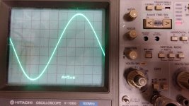
It took me the better part of two nights and half of today, but I finally figured out where the L-ch high freq oscillation was coming from. It ended up being R3 in the L channel ground circuit. That is supposed to be a 56r resistor, but it was measuring 6k. After replacing that bad resistor the L-ch is as clean as the R-ch. I included a pic of the scope with the same 20khz sine at about .8vpp that displayed the oscillation in my previous post.
Now that the ground resistor issue has been corrected, there is not a hint of oscillation. DC offset is now even lower than it was as a Quasi-Comp. Both channels are about 5 - 7mv. I rebiased the outputs and I played the amp through my 4 ohm bookshelf speakers for about an hour. The amp appears to be very quiet, no thumps or noises at power on/off.
After I finished with the listening test I installed the wattsabundant speaker protect relay pcb. I tested it and it drops out with 40VAC RMS at 6Hz, and about 2Hz when I drop the output to 30VAC rms.
I have a question for you guys that have converted these to Full Comp. What have you found to be a good bias setting? I tried 10mv Vre (which are .33r), but it appears that is going to be too high based on the temp of the heat sinks after about 30 min of playing into a 4 ohm speaker.
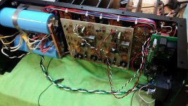
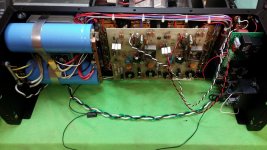
Anyway, I'm just buttoning things up now. I included a picture of the amp as it sits now with the relay pcb installed.
Now that the ground resistor issue has been corrected, there is not a hint of oscillation. DC offset is now even lower than it was as a Quasi-Comp. Both channels are about 5 - 7mv. I rebiased the outputs and I played the amp through my 4 ohm bookshelf speakers for about an hour. The amp appears to be very quiet, no thumps or noises at power on/off.
After I finished with the listening test I installed the wattsabundant speaker protect relay pcb. I tested it and it drops out with 40VAC RMS at 6Hz, and about 2Hz when I drop the output to 30VAC rms.
I have a question for you guys that have converted these to Full Comp. What have you found to be a good bias setting? I tried 10mv Vre (which are .33r), but it appears that is going to be too high based on the temp of the heat sinks after about 30 min of playing into a 4 ohm speaker.
Anyway, I'm just buttoning things up now. I included a picture of the amp as it sits now with the relay pcb installed.
Attachments
Bias would be 350mV to 450mV across the 10 ohm driver resistor with the original factory PCB. If you try and bias the output section so there is no visible crossover distortion (At 1 Watt @ 20kHz), the heat sink will warm up fairly quickly. The output transistors are basically "off" with this bias setting.
Last edited:
1 to 3 mV across Re. 10mV is more "Typical" class AB, but at 100 volt supply that's just too much idle dissipation unless you're running that PL with a fan. Crossover distortion will be lower at the high-ish bias, but not THAT mcuh lower.
The original QC circuit is unstable with some output transistor combinations at low bias. QC triples on 70 to 100 volt rails are very temperamental - and the more outputs in parallel the worse they are. The same output circuit on 30-40 V rails is rock stable at any bias. In the PL, it has to be run at zero bias or up well above that 10mV you were trying - and that gets HOT. Of course you can run the full comp circuit at zero bias, but you don't need to anymore.
The original QC circuit is unstable with some output transistor combinations at low bias. QC triples on 70 to 100 volt rails are very temperamental - and the more outputs in parallel the worse they are. The same output circuit on 30-40 V rails is rock stable at any bias. In the PL, it has to be run at zero bias or up well above that 10mV you were trying - and that gets HOT. Of course you can run the full comp circuit at zero bias, but you don't need to anymore.
..... about 50mv of 1.5Mhz noise riding on the L channel signal.
Are you sure it's not oscillation?? I wouldn't call a clear 1,5Mhz "noise"...
Perhaps somewhere a extra capacitor is needed ...
Bias would be 350mV to 450mV across the 10 ohm driver resistor with the original factory PCB. If you try and bias the output section so there is no visible crossover distortion (At 1 Watt @ 20kHz), the heat sink will warm up fairly quickly. The output transistors are basically "off" with this bias setting.
450mV across the 10 ohm is about the point that the outputs start to conduct.
At 400mV and below there is a fair amount of crossover distortion, but by 450mV its gone. I may try it at 440 - 450mV for a while and see how hot it runs with some extended listening sessions.
Are you sure it's not oscillation?? I wouldn't call a clear 1,5Mhz "noise"...
Perhaps somewhere a extra capacitor is needed ...
That problem has been repaired, see post #88.
I finished up the amp tonight. Boy this was a big project! I knew it would be, I just didn't expect the learning curve to be so high. I've still got to put the face plate on, but I finished up a couple of hours of driving it at 100W rms into a dummy load at various frequencies. It looks like 425mv of bias should be just about right.
A summarized list of the changes I did to the control pcb is as follows.
> Installed MPSA 18 input diff pair (Q1/Q2) in place of TIS97's
> Installed emitter degen resistors on Q1/Q2, I used 100 ohm as the larger values recommended by Steve Mantz exacerbate DC offset if the pairs aren't extremely well matched.
> Installed MPSA 92 for the Q3/Q4 pair in place of 2N5401/MPSA93 pair
> Replaced most of the front end resistors with RN60D metal films.
> Replaced C22/C23 with larger 4.7uF electrolytics
> C22 bypassed with .1uF/100V film
> Replaced C6 with 220uF bypassed with .1uF film and anti-parallel diodes to minimize chances of rail latch-up.
> Replaced all other electrolytics with Panasonic FC's of the same value.
> Pos & Neg rail bypassed with .01uF/250v WIMA MKP's
> Installed 2N5088's (recommended by Joe at White Oak) in place of the 2N3403 bias temp control transistors.
> Rebuilt the bias network to match the later PL36 control pcb.
> Installed 2N3440/2N5415 in place of the Q10/Q7 (40327 & 4033)
> Added 60r 1/8W base stopper resistors to Q7/Q10
> Added 2.2r 1/2W base stopper resistors to Q11/Q12
> Replaced C1 & C7 with silvered mica caps (recommended by THD+N)
> Moved signal input to the top of the control board right at the input pair.
> Moved feedback pickup points to the relay protect pcb.
I did not need to add base stopper resistors to the output transistors. This was recommended by Steve Mantz to eliminate oscillation, but was not needed on this amp.
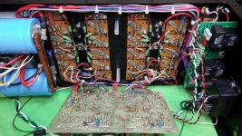
In addition I rerouted all high level signal wiring and grounds to the top of the chassis. This left only the control pcb low level wiring at the bottom to hopefully minimize noise pickup. I also rebuilt the grounding to a more modern topology with the main chassis ground and circuit common star ground isolated by a 10 ohm NTC thermistor.
I attached a few more pictures of the amp and rebuilt back plane.
I appreciate all of the help and tips by everyone. THD+N thanks for the pictures of your conversion. That was big help! I used those pictures to quadruple check that I had done everything correctly on my backplane wiring.
A summarized list of the changes I did to the control pcb is as follows.
> Installed MPSA 18 input diff pair (Q1/Q2) in place of TIS97's
> Installed emitter degen resistors on Q1/Q2, I used 100 ohm as the larger values recommended by Steve Mantz exacerbate DC offset if the pairs aren't extremely well matched.
> Installed MPSA 92 for the Q3/Q4 pair in place of 2N5401/MPSA93 pair
> Replaced most of the front end resistors with RN60D metal films.
> Replaced C22/C23 with larger 4.7uF electrolytics
> C22 bypassed with .1uF/100V film
> Replaced C6 with 220uF bypassed with .1uF film and anti-parallel diodes to minimize chances of rail latch-up.
> Replaced all other electrolytics with Panasonic FC's of the same value.
> Pos & Neg rail bypassed with .01uF/250v WIMA MKP's
> Installed 2N5088's (recommended by Joe at White Oak) in place of the 2N3403 bias temp control transistors.
> Rebuilt the bias network to match the later PL36 control pcb.
> Installed 2N3440/2N5415 in place of the Q10/Q7 (40327 & 4033)
> Added 60r 1/8W base stopper resistors to Q7/Q10
> Added 2.2r 1/2W base stopper resistors to Q11/Q12
> Replaced C1 & C7 with silvered mica caps (recommended by THD+N)
> Moved signal input to the top of the control board right at the input pair.
> Moved feedback pickup points to the relay protect pcb.
I did not need to add base stopper resistors to the output transistors. This was recommended by Steve Mantz to eliminate oscillation, but was not needed on this amp.
In addition I rerouted all high level signal wiring and grounds to the top of the chassis. This left only the control pcb low level wiring at the bottom to hopefully minimize noise pickup. I also rebuilt the grounding to a more modern topology with the main chassis ground and circuit common star ground isolated by a 10 ohm NTC thermistor.
I attached a few more pictures of the amp and rebuilt back plane.
I appreciate all of the help and tips by everyone. THD+N thanks for the pictures of your conversion. That was big help! I used those pictures to quadruple check that I had done everything correctly on my backplane wiring.
Attachments
Ok, missed that 😉That problem has been repaired, see post #88.
Chamberman,
I'm glad you saw it through to the end. I hope you enjoy(ed) the amp while you had it. Are you sure you want to give it back to your friend now?
If you want to convert another one, now you have the expertise to do it.
For a substitute bias transistor, I have used a 2SC3421 (Many other similar types can be used as well). Snip the original factory wires close to the 2N3403 so you have as much wire length as possible to work with. The wires solder easily to the larger TO-126 package and then heat shrink them for protection. The TO-126 package also lends itself to mount easily on the PL chassis.
Last edited:
Chamberman,
I'm glad you saw it through to the end. I hope you enjoy(ed) the amp while you had it. Are you sure you want to give it back to your friend now?
I still have the amp for now. I plan to hang on to it for at least a couple of more weeks to fully test it before giving it back. I got a QA400 for father's day and aside from loopback testing and cal I haven't done anything with it yet. I may give it a trial run with this amp to see how it measures.
If you want to convert another one, now you have the expertise to do it.
Its possible I may work on one for myself now! Maybe I'll find a dead one to resurrect. I'm going to wait for winter though, it's getting toasty out at my work bench in the garage.
Ha! Been there done that with the garage workshop. Now our 4th bedroom is an air conditioned workshop.
Phase Linear 700B HELP!
Hi boys Ive been lurking on this site for a while . I,m a mech engineer with basic electronics experience . So be gentle with me!! I have a phase 700B with one distorted channel The the other channel is fine Ive replaced a set of 10 outputs with MJ15024 devices I built the other channel from undamaged original xpl910 Just wonderig if the distortion is coming from the RCA410 drivers Easy way is to swap the drivers from the good channel. Is there a straight replacement device for RCA 410 I should change them out any way as theyre 30 years old now any and all advice is welcome I,m thinking the white oak board might be a good idea rather than re capping the original any help welcome Regards Terry Australia
Hi boys Ive been lurking on this site for a while . I,m a mech engineer with basic electronics experience . So be gentle with me!! I have a phase 700B with one distorted channel The the other channel is fine Ive replaced a set of 10 outputs with MJ15024 devices I built the other channel from undamaged original xpl910 Just wonderig if the distortion is coming from the RCA410 drivers Easy way is to swap the drivers from the good channel. Is there a straight replacement device for RCA 410 I should change them out any way as theyre 30 years old now any and all advice is welcome I,m thinking the white oak board might be a good idea rather than re capping the original any help welcome Regards Terry Australia
Based off of my admittedly limited experience with this amp, I'd say get rid of the XPL910's with a set of MJ15024's to match the other channel just to get started. When you say "distortion" are you seeing this on a scope/distortion analyzer or is this audible distortion?
- Home
- Amplifiers
- Solid State
- Phase Linear 700b refurb and full complementary conversion