....I modified an original 400 in the following manner (and it seems to be running and sounding great. Measurements have confirmed it is stable and distortion is very low):
1. Changed the output stage from a triple Darlington to a standard emitter follower full comp stage.
2. Deleted the RCA410 driver transistors.
3. Rewired RCA410 driver transistor sockets to accept another output device.
4. Outputs - MJ15024/25, drivers - 2SA1306B/2SC3298B (Just happen to have a bunch of these)
5. Modified bias circuitry.
6. Bias is set for about 20mA thru each output device.
7. Protection circuit was not modified. I was going to tweak it but never got around to it. It still appears to work, but I have not recalculated its protection limits.
The distortion (nominal - 0.03% I think, maybe lower. It's been 12 years since I did the mod) is now flat across the frequency spectrum at 1 Watt and does not rise after 1kHz like the original circuit. Heat sink gets slightly warm while sitting with no music signal. Power output is the same as the original into 8 Ohm loads. 4 Ohm is slightly higher.
The sound is definitely different. Much smoother and more "transparent" if I were to choose an audiophile adjective.
Do you have a schematic of the changes?

View attachment Phase Linear 400II_700II Full Comp_Page 1.PDF
View attachment Phase Linear 400II_700II Full Comp_Page 2.PDF
View attachment Phase Linear 400II_700II Full Comp_Page 3.PDF
View attachment Phase Linear 400II_700II Full Comp_Page 4.PDF
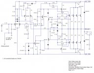
Here are the schematics from the PL service bulletin for conversion to full comp.
View attachment Phase Linear 400II_700II Full Comp_Page 2.PDF
View attachment Phase Linear 400II_700II Full Comp_Page 3.PDF
View attachment Phase Linear 400II_700II Full Comp_Page 4.PDF
Here are the schematics from the PL service bulletin for conversion to full comp.
There are errors on the supplied schematics. I don't know if they were intentional (Doubt it), but the errors have caused a lot of confusion for DIYers.
The positive drive / rail connections are correct for both 400II an 700II conversions.
The errors are in the negative drive / rail connections - 3 / 17 / 28 and 29 are the connections in question referring to the driver circuit schematic (Marked as Page 2 here in the forum listing).
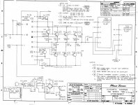
Referring to the 400II output stage schematic (Page 3)
1. Connection 3 and 17 should go to the fused side of the negative power supply rail which is not shown correctly. Shown, 3 and 17 go to the base of Q108 which is incorrect.
2. Connection 28 and 29 should go to the base of Q108.
The positive drive / rail connections are correct for both 400II an 700II conversions.
The errors are in the negative drive / rail connections - 3 / 17 / 28 and 29 are the connections in question referring to the driver circuit schematic (Marked as Page 2 here in the forum listing).
Referring to the 400II output stage schematic (Page 3)
1. Connection 3 and 17 should go to the fused side of the negative power supply rail which is not shown correctly. Shown, 3 and 17 go to the base of Q108 which is incorrect.
2. Connection 28 and 29 should go to the base of Q108.
I had to take a break from the PL700 for a few days. One of my 20+ year old Adcom car amps bit the dust. My commute to work is only about 20 - 25 minutes, but as I found out sitting in silence for that amount of time twice a day sucks. I spent my free time this weekend repairing that. Now that project is done and I have entertainment for my commute once again so I can refocus on the PL700.
Nick, Thanks for the additional info and schematics on your modded PL amp. It looks interesting. I like the added low impedance drive capability you worked into the output stage. I wish you were more local I'd like to give it a listen. Just in case someone wanted to see the proper connections on the factory PL full comp amp. I used MS paint to correct the errors on PG3 of the PL400II full comp factory schematics that Nick posted previously. This would of course apply to the PL700 as well.
Nick, Thanks for the additional info and schematics on your modded PL amp. It looks interesting. I like the added low impedance drive capability you worked into the output stage. I wish you were more local I'd like to give it a listen. Just in case someone wanted to see the proper connections on the factory PL full comp amp. I used MS paint to correct the errors on PG3 of the PL400II full comp factory schematics that Nick posted previously. This would of course apply to the PL700 as well.
Attachments
Okay I was finally able to make the amp unstable.
I was finishing up the control pcb and just before I replaced Q7/Q10 I hooked up the scope and checked the output and it was solid and looking good. After I replaced Q7/Q10 with the new 2n3440/5415 pairs the right channel had a bit of oscillation. The left however looks great. So it looks like these new transistors are a little faster than the old MM4003/40327 pairs that they replaced. This is even with a 60 ohm base stopper resistor on Q7/Q10. I installed that before the Q7/Q10 change out. Interestingly enough, the oscillating right channel has the XPL910'S in it and the non-oscillating left has the FPL909's.
I decided to try Mantz suggestion in the post I linked to earlier in the thread and I pulled C10 in the right channel and installed a 22pf from B to C on Q5. No, that didn't work.. Oscillation was probably 2X as bad, so I reinstalled C10. At this point I have a few things I'm going to test to see how they affect the oscillation. However I plan to proceed regardless. Due to the fact the entire output stage is going to be replaced and all of the low level wiring is going to be isolated from the high level stuff I think that things may straighten out with those changes. If it doesn't at least I tested it enough that I know at which point the front end became unstable.
I tried swapping out the Q7/Q10 60 ohm base stop resistors for some 82 ohm ones. This brought the oscillation down marginally. I am going to hold off on any other changes for now. I am highly suspicious of the xpl910 darlingtons in this channel. Like I was saying earlier the channel with the fpl909's looks great. I will see if the issue clears up after the conversion. If its still there then I'll back up and install the added capacitance from B to C on Q7 & 10.
I would be suspicious of those XPL910's too.
In addition, I have never been a fan of having different outputs in each channel, even though the guys at PL said it was OK. Technically, it should be OK, but I would never do it because it would bug me knowing there are two different types of output devices (OCD?).
In addition, I have never been a fan of having different outputs in each channel, even though the guys at PL said it was OK. Technically, it should be OK, but I would never do it because it would bug me knowing there are two different types of output devices (OCD?).
I'd temporarily throw a set of MJ15024's in there. Supposedly, those XPLs were one of the worst transistors they ever used in those things. I've had almost everything else in the ones I've had - Moto, Faichild, RCA, and NEC. Including various mixes between channels and a couple of non-standard replacements in the 400.
I'd temporarily throw a set of MJ15024's in there. Supposedly, those XPLs were one of the worst transistors they ever used in those things. I've had almost everything else in the ones I've had - Moto, Faichild, RCA, and NEC. Including various mixes between channels and a couple of non-standard replacements in the 400.
I would do that if it weren't such a pain in the ****, mica and grease, etc. At this point it'd just be a test that I'd have to take back apart when I move everything to the new WO chassis. I don't want to spin my wheels too much beyond what's necessary.

Speaking of mica and thermal compound... most people use too much. If you have compound oozing out like filling your ball joints on your car, then you have used too much.
It takes some experimentation, but you can get away with just enough so it barely oozes out and yet there is enough there for it to do its job.
In addition, any extra compound will likely end up on "everything" before long after touching it.
It takes some experimentation, but you can get away with just enough so it barely oozes out and yet there is enough there for it to do its job.
In addition, any extra compound will likely end up on "everything" before long after touching it.
Apply a VERY thin film to both sides of the mica with a razor blade. The proper amount will hold the transistor with surface tension and make it difficult to remove - or even move for that matter. If you remove the screws after tightening them, and it won't budge (and you have to consider prying it up with a screwdriver tip if you needed to remove it) then you have it right.
For the 'quick test' I suggested above, i would use greaseless silicone pads. I like the thermal performance and reliability of mica/grease better (sil pads often cut through) and would use that for a final install.
For the 'quick test' I suggested above, i would use greaseless silicone pads. I like the thermal performance and reliability of mica/grease better (sil pads often cut through) and would use that for a final install.
I had a bit of a set back last night. I was going to begin tearing down the old chassis and I decided to take one more DC offset measurement before I began. L ch -20mv, R ch 650mv. Hmmmmm.... I hadn't done much since the last good measurement. So I started inspecting and going back through everything I had done. I even swapped the MPSA18 input pair out thinking maybe I had done something to blow them. After about an hour and a half of checking and inspecting I finally found a small solder bridge on one of the traces. It had fallen on a through hole component and spread out to where it managed to touch an adjacent trace. The funny thing is it looked like it was possibly supposed to be there. It wasn't until I looked closely under the magnifying lens that it was clear that it was not supposed to be there. After removing the solder bridge the DC offset dropped to -12mv, even better than before because I installed a new pair of MPSA18's that matched a bit better.
I'm glad I caught that issue before I proceeded. I would have suspected my backplane upgrade work as the cause if I had found it later. I'm sure I'd have wasted a lot of time isolating the problem then.
I'll post a few pics of the new chassis later. It looks real nice and is much stouter than the old PL700 flexy chassis.
After all this "work" are you sure you are going to want to give this amp back to your friend? It has become a labor of love.
Those solder blobs we get you...
Those solder blobs we get you...
After all this "work" are you sure you are going to want to give this amp back to your friend? It has become a labor of love.
Yeah I know... Hopefully the sound quality is worthy of the labor.
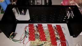
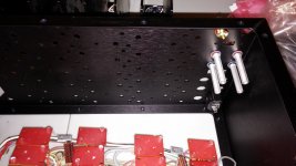
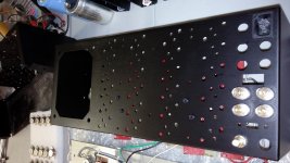
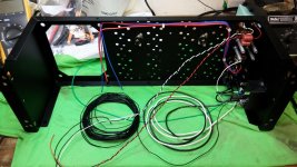
Here are a few pics of the new White Oak PL700 chassis before I begin building it up. As you can see the new binding posts are in and one of the Vampire RCA's I'll be using. The chassis is all aluminum with boxed & welded corners as well as threaded inserts for the covers and temp switches.
Attachments
Making a bit of progress on this PL700 refurb and full comp conversion. I have the wiring just about completed and will be starting on the backplane soon. I installed a new slide switch for the DC/Capacitively Coupled selector. I found that mouser PN 10SS002-EV is an exact replacement and its only a little over $1. Its actually nicer in that it has a threaded mounting plate and doesn't need backing nuts like the original. The original coupling caps were also replaced with 2.2uF Panasonic metallized polypro's. The large relay (30A contacts) will be the new power contactor replacing the original undersized microswitch. I'll be wiring the temp switches into the relay coil circuit so it'll still shut down in the event of an over temp.
Attachments
I put in about 8 hours on this PL700 today and I'm about 95% of the way completed now.
I have already gone through the safe power up stages and I now have all of the outputs in and the dim bulb is now out of the circuit. The only problem I've run into is that its not biasing up. Needless to say I have some sizable crossover distortion. I tried changing out R19 from a 1k to a 2.1k to see if this would give me any additional adjustment, but no luck. At the base of Q11 I have .5V minimum and .6V with the bias pot at maximium. So it looks like I need to squeeze a bit more voltage out of it.
Any suggestions?
I dropped the value of R62 from 390 ohms to 301ohms to allow more current to the base of Q6 and I still have no bias adjustment. Hmmm,, I had full adjustment of the bias on both channels before the output stage conversion. So I know that part of the circuit was working fine with RCA410's as the drivers.
- Home
- Amplifiers
- Solid State
- Phase Linear 700b refurb and full complementary conversion