Distortion at low volumes, distortion at high volumes, lost either the positive or negative half cycle? The nature of the distortion is very important.
And MJ15024 will work for both driver and output. Although the RCA410 (66546) rarely gave any trouble. The XPLs sure did - get rid of them if you're even thinking about 4 ohm speakers.
And MJ15024 will work for both driver and output. Although the RCA410 (66546) rarely gave any trouble. The XPLs sure did - get rid of them if you're even thinking about 4 ohm speakers.
One other thing while you're in there working on it, replace C6 in both channels. Both of these caps were toast in the PL20 board that I worked on and from what I understand that is fairly common. As a result bass response was severely rolled off. In one channel the roll off started at 1khz. I used a 220uF/35v because I had a bunch of them. Some folks are using 470uF. After replacing those caps the stock amp measured flat down to about 12hz.
Not to sidetrack this interesting thread... I have what I believe to be an original PL 700. It's been in pretty much continuous use since new, and is currently in my system powering my satellite systems. It sounds ok to me. Is there stuff I should be doing to it other than replacing burnt out meter and power lamps?
Replace electrolytic caps, and re-flow or re-solder any joints on the PCB that look like they are getting cooked. The Series 2's are far worse about the high power resistors cooking the board than the originals, but anything that old with 1, 2 or 5 watt resistors on a board deserves being checked for potential problems. If there is no oxidation or discoloration, leave 'em alone.
When that feedback cap goes bad, the bass goes away. Bad power supply caps cause you to lose power. And when you get a bad bootstrap cap, you'll swear the amp is haunted (symptoms will not make any sense and you''ll end up here asking WTF).
When that feedback cap goes bad, the bass goes away. Bad power supply caps cause you to lose power. And when you get a bad bootstrap cap, you'll swear the amp is haunted (symptoms will not make any sense and you''ll end up here asking WTF).
Thank you! I'll most likely get around to it some time this winter. Since it only handles 100Hz and above, I likely wouldn't notice bass missing...
Since it only handles 100Hz and above, I likely wouldn't notice bass missing...
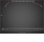
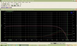
Actually depending on how bad the feedback caps are, you just might notice a big difference. See the attached L & R channel freq response plot of the amp I tested before I started the upgrade work on it.
Attachments

Phase Linear 700B Full Comp and more...
Hello All,
I bought a 700B awhile back that had seen much better days. To say it was in rough shape would be an understatement. It had mismatched meters, no center Phase Linear back light logo assembly, no front panel controls, no driver board, the front panel barely resembles the original panel - it just looks like an aluminum plate, no outputs or drivers, etc.
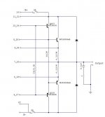
I bought it (for very cheap) with the intent of using it as a test mule to try out different circuit topologies. I rebuilt the output stage - full complimentary, but with a more modern topology. The pre-driver and driver transistors now run in Class A and the outputs are biased just slightly on. Biasing the output is a compromise of idle heat vs heat sink area vs THD+N at 1 Watt.
For now, it is biased with 4mV across the 0.27 Ohm emitter resistors, which gives you about 15mA thru the output transistors. I used 0.27's instead of 0.33's because I just happen to have more of the 0.27's on hand.
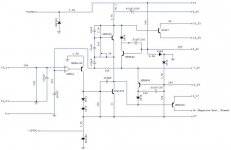
Attached are the PCB and driver/output stage schematics showing the modifications. I also changed the original Miller capacitor (100pF) to 39pF which extends the bandwidth up to 100kHz. The amp appears to be stable so far. I also had to change R106 from 680 Ohm to 560 Ohm to get slightly more bias voltage out of the Vbe circuit.
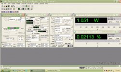
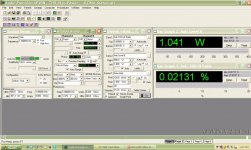
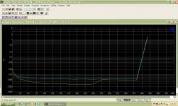
Overall, THD+N is down across the frequency spectrum and it appears to be more linear. The rise beginning at 1kHz in the original circuit is now gone. The modified circuit THD+N at 20kHz, 1 Watt is only 0.06% (Left) and 0.08% (Right).
Listening tests sound good, but I'll spare you all the adjectives to try and describe the sound difference. To me, it sounds better, especially at lower power levels. My main speakers are ported La Scala's so I don't need much power. However, I have some original Advents and they love the modded 700B.
Hello All,
I bought a 700B awhile back that had seen much better days. To say it was in rough shape would be an understatement. It had mismatched meters, no center Phase Linear back light logo assembly, no front panel controls, no driver board, the front panel barely resembles the original panel - it just looks like an aluminum plate, no outputs or drivers, etc.
I bought it (for very cheap) with the intent of using it as a test mule to try out different circuit topologies. I rebuilt the output stage - full complimentary, but with a more modern topology. The pre-driver and driver transistors now run in Class A and the outputs are biased just slightly on. Biasing the output is a compromise of idle heat vs heat sink area vs THD+N at 1 Watt.
For now, it is biased with 4mV across the 0.27 Ohm emitter resistors, which gives you about 15mA thru the output transistors. I used 0.27's instead of 0.33's because I just happen to have more of the 0.27's on hand.
Attached are the PCB and driver/output stage schematics showing the modifications. I also changed the original Miller capacitor (100pF) to 39pF which extends the bandwidth up to 100kHz. The amp appears to be stable so far. I also had to change R106 from 680 Ohm to 560 Ohm to get slightly more bias voltage out of the Vbe circuit.
Overall, THD+N is down across the frequency spectrum and it appears to be more linear. The rise beginning at 1kHz in the original circuit is now gone. The modified circuit THD+N at 20kHz, 1 Watt is only 0.06% (Left) and 0.08% (Right).
Listening tests sound good, but I'll spare you all the adjectives to try and describe the sound difference. To me, it sounds better, especially at lower power levels. My main speakers are ported La Scala's so I don't need much power. However, I have some original Advents and they love the modded 700B.
Attachments
-
 Phase Linear 400_700 original driver circuit converted to full comp_DIY.jpg53.2 KB · Views: 289
 -
 Phase Linear 400_700 original output circuit converted to full comp_DIY.jpg29.1 KB · Views: 295
 -
 700B Full Comp_Mod_1 Watt Left Analyzer Panel_DIY.jpg113 KB · Views: 279
 -
 700B Full Comp_Mod_1 Watt Right Analyzer Panel_DIY.jpg113.9 KB · Views: 173
 -
 700B Full Comp_Mod_Frequency Response vs THD+N vs Amplitude_DIY.jpg104.1 KB · Views: 155
 -
 700B Full Comp_Mod_THD+N vs Power_DIY.jpg112.8 KB · Views: 194
400+ watts with both channels driven and very low distortion = very nice!
I see you went with a series II front end, was that by design or did you have a spare laying around?
I see you went with a series II front end, was that by design or did you have a spare laying around?
BTW, 15ma seems pretty high from what I remember of the stock heatsink capacity. Did you have to put a fan on them?
I used the 400ll/700ll driver board (PL36) since I happen to have one lying around.
I had some PL36 driver boards made years ago if anybody is interested in one for a repair or whatever. These boards are an exact replacement for the original PL36 driver PCB, except I built in a bridging option too. If you don't want to use the bridging option, you can bypass this feature with jumpers on the PCB.
10 ~ 15mA seems to be OK. The heat sink gets slightly warm at idle, but it is acceptable. Anything greater than 15mA would not be recommended unless you ran a fan at low speed.
Last edited:
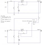
A 400/700 original series or series two can be bridged. There are various methods available to bridge an amp.
The easiest way (in a general way and not applicable to all amp designs) is to tap off of the (+) output from one channel (let's say the left) and tie this connection through a resistor (same value as used in the feedback loop) to the right channel (-) input. The "normal" right input is not used.
This is not the optimal way (DC offset is affected some, depending on amp design) to bridge an amp, but it does work and it is practically free to implement.
See attached image.
Attachments
Every amplifier with feedback has a dominant pole. That makes the amp have 90 degrees phase shift in feedback at unity gain. You can't add other poles (capacitors) to the design and expect stability. The dominant pole in the Phase Linear 700B is C10, 180pF. If you add another 100pF across that cap, oscillations will go away. I can't remember what I added to my amp 30 years ago. Carver should have placed the cap between base and collector of Q5 in parallel with that transistor's internal Miller capacitor. That way a high hfe transistor would be compensated by more negative feedback. The dominant pole usually is associated with the high gain stage of an amp, and in the 700B, that is Q5.
Thanks For the drawings,,,,,, luckily I found your post and this web page cuz I have some 400II and 700II I'm converting to full Luckily I have a one 700II full for Refences, Do you have any recommendation for to reduces any High or low FHZ noise? and to add or change any capacitors?View attachment 487077
View attachment 487078
View attachment 487079
View attachment 487080
Here are the schematics from the PL service bulletin for conversion to full comp.
Note -Board 700II R127\R227 =56k 400II =82k and a bunch of resistors need to be remove and some jumper added (your drawings)
Q107 and Q108 -700II R139=180Ohm and R140=150Ohms
Brings up a bunch of Questions for the new PNP output Bus, (NPN side looks to be ok and no rework and one wire) I but the PNP Side , I know 2-resistors need to be added R111 or R127
does the R140 and emitter Resistors work as is? or flip the resistor B to C ? WOW thinking out loud The Collator Resistor are flipped and is this a lot of work on the PNP side ? (- DC output Rail has the resistors now) need to be moved ,Flipped ? Do you Remember doing any major rework w the Resistors ? How much rework is their?
(I will have to also double check my 700II full and compare it to a 700II Quad)
Thanks Steve
As I recall, when I've converted to a full comp I reverse the PNP predriver on the board. Kind of tricky when using a TO5 package but doable.
Thanks
Good to know,,,, I will have to add that to the list and check all of them , and compare the drawing and the one I already have (700II)
looks like all the outputs will work I hope as is But I will also have to double check and see were the collector is and output Resistors
how's your running? was it worth it?
I'm working on that ground input network I currently have just a little buzz and add will add a new shield Cable and might take out the 120vac outlet and wire the temp sw's to my speaker protect board to get ride of the Ac but I'm not done yet. every time I do something a wire comes off and short something LOL and going to add flexible new wires from the board to back bus and longer
Thanks again for the drawings
As for the grounding network, P/L tied the RCA input ground to the output binding posts. The preferred method has separate grounding conductors for the input jacks and one for each black output binding post all of which are landed on the ground bus bar on the DC caps. Chassis is tied to the bus bar at one point only. The inputs are isolated from the chassis via the 3/8" fiber washers on the RCA jacks.
Actually did it that way, (good to know ) I also tried it w/o the RCA - not hooked up to the buss and only going to the board and and it did not work. rehooked it up back up to the 0vdc Buss and it worked (I install 2/4 long new shielded Cables)
I going into this w Great Detail. Their is no ground in the phase linear amp and the N (Ground Level) goes to the the primary side of transformer and ends their. The secondary side is not grounded ant not grounded to the frame and Chassis. The Buss Bar is centered by the transformer and is a 0vdc bus and would be considered a floating ground. their are other ground loop also, that I found.
Still working on Grounding this Amp and a AC ground. and Maybe even a isolation ground Bar.
If I do nothing and the amp is grounded by the RCA input ground and from a upstream Audio Device
(not the best ground)
Its fun so far and will not stop at just this amp (upstream too)
- Home
- Amplifiers
- Solid State
- Phase Linear 700b refurb and full complementary conversion