Hello. Do you know the difference between these two ways of applying feedback from the OT?
What would be the best method ?
Does one allow better PI performance than the other ?
Which one is lower noise ?

I am grateful for your help.
What would be the best method ?
Does one allow better PI performance than the other ?
Which one is lower noise ?
I am grateful for your help.
Two of your questions are about "better". What do you consider better to mean? These are guitar amps, not hifi amps, so there are no standards of performance to measure against. I am not being picky, but if we know what you would consider better, we can answer easier.
I am not well versed in guitar amplifier. I choose these 2 schematics because they have the same name.
I was reasoning in term of PI functionality, the PI is almost 100% the same on the two design, but the feedback is applied differently. Why ?
Does it sound different ?
Is one less noisy than the other ?
By better I mean is there a reason for doing it one way above the other.
By better I mean, is there any benefits of choosing the first or the second.
Thank you for taking the time
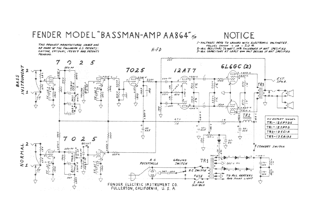
The 864 plan is far more popular.
But if you are not well versed in guitar amps, either plan is challenging. And really too powerful for most stages today. A DeLuxe is a better first build.
But if you are not well versed in guitar amps, either plan is challenging. And really too powerful for most stages today. A DeLuxe is a better first build.
Hi thank you PRR.
I was misunderstood. I don't plan to build any of them. I was googling "Phase Inverter Feedback" and found a website talking about converting the 164 into a 864.
I was just wondering about the difference in negative feedback location, but I was afraid to post in the "hifi" forum, because they would tell me "those schematic are instrument amps and don't belong in this section". So I tried posting here.
I just wondering about the NFB location. Since the 864 is the better amp and probably a newer revision, is is safe to assume that the nfb is at a better location? Probably more optimized for lower noise too?
Hi thank you PRR.
I was misunderstood. I don't plan to build any of them. I was googling "Phase Inverter Feedback" and found a website talking about converting the 164 into a 864.
I was just wondering about the difference in negative feedback location, but I was afraid to post in the "hifi" forum, because they would tell me "those schematic are instrument amps and don't belong in this section". So I tried posting here.
I just wondering about the NFB location. Since the 864 is the better amp and probably a newer revision, is is safe to assume that the nfb is at a better location? Probably more optimized for lower noise too?
The AA864 is older than the AB865. The difference in NFB locations is likely to be subtle. I would go for the NFB location at the tail, the AA864 location.
The method shown below is the better one, it is used in 99.99% of long tail phase inverters, and is equivalent to a non inverting Op Amp configuration, the big advantage being a high input impedance, so the stage driving it has the same duty and performqance as of any other tube stage.
The WELL trodden road.
In 51 years building MI amplifiers never ever saw the top one and wouldn´t if you hadn´t posted it.
It´s equivalenht to an inverting Op Amp configuration.
"Nobody" uses it (0.01% accounts for that) for two very good reasons.
1) it offers very low input impedance, a bitch to drive for any standard tube stage.
2) NFB and gain are "indefinite" , since the first leg of the NFB net is the driving tube internal impedance, which varies from tube to tube and also with aging.
I bet a new Engineer sat at a bench and thought "let´s do something different, just for the sake of it"
Last edited:
The method shown below is the better one, it is used in 99.99% of long tail phase inverters, and is equivalent to a non inverting Op Amp configuration, the big advantage being a high input impedance, so the stage driving it has the same duty and performqance as of any other tube stage.
The WELL trodden road.
In 51 years building MI amplifiers never ever saw the top one and wouldn´t if you hadn´t posted it.
It´s equivalenht to an inverting Op Amp configuration.
"Nobody" uses it (0.01% accounts for that) for two very good reasons.
1) it offers very low input impedance, a bitch to drive for any standard tube stage.
2) NFB and gain are "indefinite" , since the first leg of the NFB net is the driving tube internal impedance, which varies from tube to tube and also with aging.
I bet a new Engineer sat at a bench and thought "let´s do something different, just for the sake of it"
Never even thought about it in terms of impedance, now looking at it knowing, no way would I even consider it. Mind you, with the lower impedance you will have to drive your preamp harder.
It also has a silly Leo-Fender mistake in it: the 22k tail resistor really should be connected directly to ground, not to the top of the 100-ohm feedback resistor.The (second) method shown below is the better one, it is used in 99.99% of long tail phase inverters
Guitar amps use so little negative feedback that, in practice, this won't make any significant difference. But it's irritatingly "wrong" to anyone who knows how you actually connect an long-tailed pair input stage to make inverting and non-inverting amplifiers. Rather like mounting the steering wheel in your car upside-down when the wheels are pointed straight ahead.
Merlin Blencowe speculates that Fender came up with this weird little error - subsequently blindly copied by many other Fender-copycats- because Leonidas was trying to use an existing turret-board layout with a newly revised schematic.
-Gnobuddy
It also has a silly Leo-Fender mistake in it: the 22k tail resistor really should be connected directly to ground, not to the top of the 100-ohm feedback resistor.
Guitar amps use so little negative feedback that, in practice, this won't make any significant difference. But it's irritatingly "wrong" to anyone who knows how you actually connect an long-tailed pair input stage to make inverting and non-inverting amplifiers. Rather like mounting the steering wheel in your car upside-down when the wheels are pointed straight ahead.
Merlin Blencowe speculates that Fender came up with this weird little error - subsequently blindly copied by many other Fender-copycats- because Leonidas was trying to use an existing turret-board layout with a newly revised schematic.
-Gnobuddy
The amount of NFB does not have to be much, just enough. We can hear the difference between with and without, an excess makes it start to sound like a transistor amp.
What Gnobuddy IMHO was trying to point out is something that has also made me thinking of: Inserting NFB into a LTP's tail means NFB for the 2nd triode, but it also means PFB for the 1st one! Though it really does, I've also been wondering how this works really?
Anyway, just returning the tail resistor to gnd would make it much more clearer!
Best regards!
Anyway, just returning the tail resistor to gnd would make it much more clearer!
Best regards!
Last edited:
To be clear - I wasn't saying Leo's mistake was having too little NFB.The amount of NFB does not have to be much, just enough. We can hear the difference between with and without, an excess makes it start to sound like a transistor amp.
Leonidas' mistake is that the negative feedback signal is connected both to the second triode's control grid, and also to the "long tail" in the long tailed pair. It should go only to the second triode's control grid.
For a differential gain stage, aka "long tailed pair" to work, the "long tail" is supposed to act as a constant current source, or as much like one as possible. Injecting a signal voltage into the far end of it - and thus making it not a constant current - makes absolutely no sense whatsoever.
This is just plain wrong, as Kay also pointed out. It is an error, plain and simple. Fortunately, the amount of NFB in this amp is so low that this error had no significant bad consequences.
-Gnobuddy
Injecting NFB at the tail makes the distortion profile "more interesting".
"...guitar electronics isn't really electronics per se. It's part electronics and part psychoacoustics and part personal preference (musical taste). It seems there isn't a textbook way to get what you want. So there's been a lot of blind tinkering over the decades."
"...guitar electronics isn't really electronics per se. It's part electronics and part psychoacoustics and part personal preference (musical taste). It seems there isn't a textbook way to get what you want. So there's been a lot of blind tinkering over the decades."
Last edited:
Maybe...but has anyone actually checked this?Injecting NFB at the tail makes the distortion profile "more interesting".
Looking at the mix-up a bit more closely, the small-signal impedance at the shared cathodes of the LTP triodes is pretty low, there's a 22k tail resistor in the way before the accidental screwed-up feedback gets to those cathodes, and there's little enough feedback to start with.
So is there enough of the accidentally screwed-up feedback signal at those LTP cathodes to cause any audible difference at all? My gut says "No!", but I haven't done anything to prove it one way or the other. I just take these stories with a spoonful of skepticism until they're proven to be true.
It does also appear to be the case that for every mistake Leonidas made (the horrific "interactive" tone and volume controls in a 5E3, say), there are a dozen tales on the 'Web about the sweet music-mojo it imparts. 😀
I'm going to go tie a string from the steering wheel of my car to the gas pedal, so that the steering and accelerator controls become "interactive". I bet this will add sweet mojo to the driving experience! 😀 😱
-Gnobuddy
Isn't the 100ohm here to lower the negative feedback?
Also what is the effect of lowering the Second coupling capacitor the 0.1uF ?
It is a DC stabilization, but on bass do you have more "inverted bass signal" to the second grid ?
Edit : sorry guys I know guitar is more about distortion style, but I am looking for more hifi analyses just to understand better how it works.
Last edited:
The 820 ohm and 100 ohm feedback resistors together set the fraction of the output voltage which is fed back. It is their ratio that is important - you could replace them with 8200 ohms and 1000 ohms and get exactly the same result.Isn't the 100ohm here to lower the negative feedback?
The actual amount of negative feedback depends on what is called the open-loop voltage gain of the circuit: the voltage gain of the circuit if you cut out and removed the 820 ohm resistor entirely.
With the resistors in place, the voltage gain of the entire circuit decreases (due to the negative feedback.) The voltage gain with the negative feedback working is called the closed-loop voltage gain of the circuit.
The amount of negative feedback is the ratio of the open-loop voltage gain to the closed-loop voltage gain, expressed in decibels.
For example, if the open-loop voltage gain is 21 times, and the closed-loop voltage gain is 7 times, the ratio of the two is 3.0. Take the logarithm of 3.0 (to the base 20), multiply by 20, and you calculate that the circuit has about 9.5 dB of negative feedback.
I don't know exactly what this number is for the Bassman, but in tube guitar amps like this, there is usually somewhere between 3 dB and 10 dB of negative feedback.
Yes, but the existing 0.1 uF capacitor is so huge that you can reduce the second coupling capacitor a lot without affecting anything you can hear (only frequencies far below the bass guitar's output, and even further below the ability of the Bassman speakers.)...effect of lowering the second coupling capacitor the 0.1uF...on bass do you have more "inverted bass signal" to the second grid ?
The existing 0.1uF cap couples the signal through to the triode all the way down to 1.6 Hz, which is just silly. You could reduce it to 0.01uF, and that part of the circuit would still go down to 16 Hz, far below the lowest note on even a 5-string bass guitar (~ 30 Hz).
Today that's true, but not when the Bassman was new. From everything I've read, Leo Fender didn't want his amps to distort. The Bassman was designed to cleanly amplify the new Fender Precision Bass....I know guitar is more about distortion style...hifi analysis...
Unfortunately, there were major design flaws in the Bassman that made it unsuitable for that job. It turned out to be a very bad bass amp, mainly because the speakers and open-back cabinet could not handle their job, also because the cathode-follower in the preamp was badly designed (from Leo's low-distortion point of view), and actually caused lots of distortion.
But a few blues guitarists (who did want distortion) found out that the Bassman worked very well for blues guitar, and so, quite by accident, the Bassman went on to become an iconic guitar amp.
-Gnobuddy
- Home
- Live Sound
- Instruments and Amps
- Phase inverter feedback location