You were a bit quick in replying there mark100. 😱
I can only tell you what I know. We'd all love to build simple two-ways with first-order crossovers and hope for the best. Or just duck the room issue altogether and listen on the best Koss electrostatic headphones:
But a better way of doing things is a three way:
SEAS-3-Way-Classic
What Troels Gravesen did here, slightly inadvertently was all some good mathematical theory with some real-world response:
The theory:
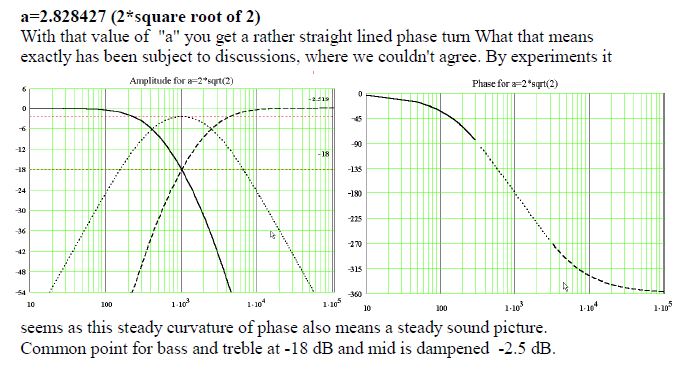
The practise:
Of course a frequency response tells you nothing whatsoever about dispersion and distortion. And time delay is only indirectly specified.
I can only tell you what I know. We'd all love to build simple two-ways with first-order crossovers and hope for the best. Or just duck the room issue altogether and listen on the best Koss electrostatic headphones:
But a better way of doing things is a three way:
SEAS-3-Way-Classic
What Troels Gravesen did here, slightly inadvertently was all some good mathematical theory with some real-world response:
The theory:
The practise:
Of course a frequency response tells you nothing whatsoever about dispersion and distortion. And time delay is only indirectly specified.
You were a bit quick in replying there mark100. 😱
I can only tell you what I know. We'd all love to build simple two-ways with first-order crossovers and hope for the best. Or just duck the room issue altogether and listen on the best Koss electrostatic headphones:
But a better way of doing things is a three way:
Gave me a good grin, thx 🙂
Not sure how you got the impression I was talking about simple two-ways...
Totally agree a 3-way is better than a two-way (if spl, and frequency extension are goals)
I prefer a 4-way because I really like spl and extension.
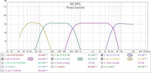
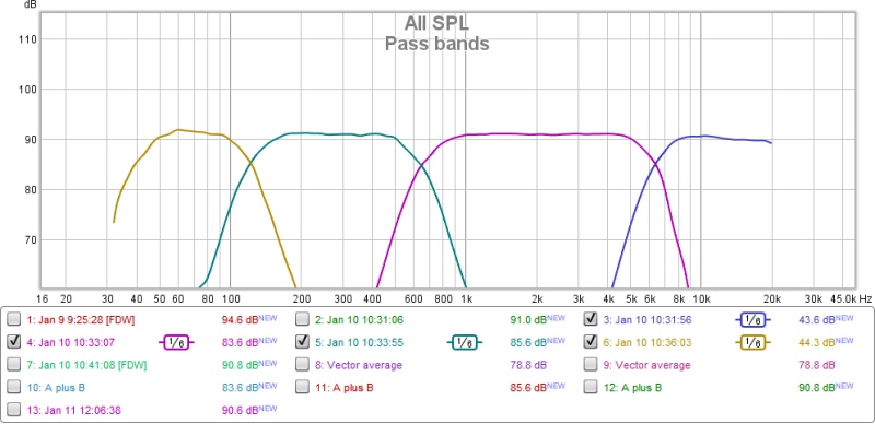
The measurement plot below is typical, for my active 4-way builds, using the xover method I've been describing.
Each of the passbands shown are acoustical measurements, not electrical.
Attachments
If you are managing to do THIS, I am totally impressed:
😀
If I was attempting to improve a simple speaker like this,
I would add a supertweeter for better high end dispersion. But that doesn't fix the 3kHz cone-breakup from the 8" bass.
We have mentioned your classic 3-way. Not bad:
SEAS-3-Way-Classic
I also enjoyed this dome-midrange speaker using the difficult Scan 6" bass:
SP38/13
That, IMO, is a hard one to get sounding right. A 2-3" dome-mid falls apart into breakup around 5kHz. It is also hard to align to a bass without crossover complexity. Troels does a splendid job there.
Bravo! 🙂
Hi Steve, thank you.
Yes, it's become very easy to achieve results like that...
That's kinda why I keep belaboring the method i find so simple ....relative to what to me seems like more traditional, but complicated methods..
Yes, it's become very easy to achieve results like that...
That's kinda why I keep belaboring the method i find so simple ....relative to what to me seems like more traditional, but complicated methods..
The measurement plot below is typical, for my active 4-way builds, using the xover method I've been describing.
Each of the passbands shown are acoustical measurements, not electrical.
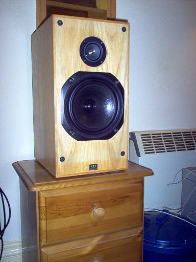
May we see your plot without smoothing? A photo of the speaker would be good too!
May we see your plot without smoothing? A photo of the speaker would be good too!
Yep, I'll dig some up.
May we see your plot without smoothing? A photo of the speaker would be good too!
TBH, it does look a bit TOO perfect:
But no criticism implied. Just a four way is totally beyond my experience. 😱
I was astonished by the Steen Duelund three-way:
All three drivers are perfectly phase aligned. And all that really matters is the centre frequency.
Of course, between the idea and the actuality falls the shadow:
Real world drivers are not so perfect.
But you've made me think about this modest speaker:
I certainly like that cone tweeter, but would prefer to cross it above 4kHz rather than 3kHz. And let a supertweeter take over around 10KHz. And I don't like the 3kHz cone-breakup from the 8". So a mid is indicated from 600Hz to 4kHz, and that's not hard.
This is good. 😀
Could do with more bass?
Yeah for sure. That was a old plot (when I needed smoothing 🙂 just to show 4 passbands to System7.
It was a PA setup that didn't need real low extension.
I've since built and use subs that are f-3 at 30Hz, which is good enough for me as I don't came about HT.
I quit making such passband plots, as tuning became too easy, and I felt silly in just showing pretty graphs.....
But I do have alot of full 4-way plots that I'll find and look thru, to illustrate the tuning method's efficiency...on several different designs.
Yes, the goal is to get an exact LR2, LR4 or whatever slope you want out of your drivers acoustically.
The easiest method is with DSP. You flatten the driver's frequency response, then apply the desired slope.
I think the goal is to produce two (or more) band limited signals, the sum of which is exactly equal to the full-band input. And that is impossible with two analog filters, both of greater than first order. It is possible with a digital filter because a digital filter can include an overall delay, which provides signal (taps) from the future as well as the past. Analog filters are based on the past signal history only, hence the phase shift.
At the start of this thread, I tried to introduce the idea of signal windowing as a more sophisticated understanding of a "pulse" and suggested the SPICE simulation, but it seems it was wasted on MW (etc).
So lets just say that any analog filter, including passive XOs, is a compromise. You have to decide between phase and amplitude anomalies, and driver protection. Perhaps the best compromise is a first order (choke only) filter on the low pass because the high frequencies will not damage the larger driver. And the high impedance at high frequencies can be useful to dampen the cone resonances. But that gets into a more complex model of the speaker behavior which is probably not useful here.
At the start of this thread, I tried to introduce the idea of signal windowing as a more sophisticated understanding of a "pulse" and suggested the SPICE simulation, but it seems it was wasted on MW (etc).
Sadly my basic knowledge of analogue electronics and passive crossovers is very poor, which is mainly why I'm entering the world of DSP. So yes, it was was wasted on me, but probably not on others. Sorry, my failing.
The straightforward answer to the relationship between phase and group delay in causal filters is exemplified here:
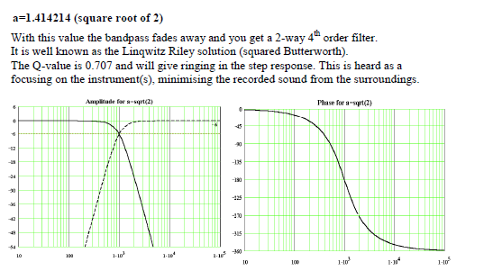
This is a fourth order Linkwitz-Riley filter.
The phase (phi) is a function of the transfer function or rolloff slope of frequency w (omega).
The Group delay Tg is the slope of the phase wrt frequency = - d(phi) / d(omega). What we call a differential relationship in calculus.
Group delay and phase delay - Wikipedia
What this is saying is the rolloff slope wrt to frequency defines the phase. The phase slope wrt frequency defines the group delay. You can tell I have a mathematical background in signal processing. 😱
Shallower LR2 slopes introduce less group delay than steeper LR4 ones. But also have more distortion in practice.
Most speakers look like this on group delay:
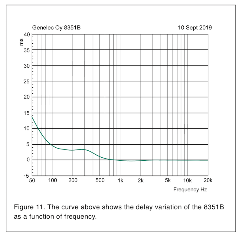
This includes a certain amount of bass slope, which complicates matters.
Digital filters can overcome some of the limitations of analog passive crossovers, but TBH, I don't care much. Group delay is not something that really destroys enjoyment of music. Distortion is a worse culprit, IMO.
This is a fourth order Linkwitz-Riley filter.
The phase (phi) is a function of the transfer function or rolloff slope of frequency w (omega).
The Group delay Tg is the slope of the phase wrt frequency = - d(phi) / d(omega). What we call a differential relationship in calculus.
Group delay and phase delay - Wikipedia
What this is saying is the rolloff slope wrt to frequency defines the phase. The phase slope wrt frequency defines the group delay. You can tell I have a mathematical background in signal processing. 😱
Shallower LR2 slopes introduce less group delay than steeper LR4 ones. But also have more distortion in practice.
Most speakers look like this on group delay:
This includes a certain amount of bass slope, which complicates matters.
Digital filters can overcome some of the limitations of analog passive crossovers, but TBH, I don't care much. Group delay is not something that really destroys enjoyment of music. Distortion is a worse culprit, IMO.
Last edited:
The straightforward answer to the relationship between phase and group delay in causal filters is exemplified here:
Well, I get the general drift, but I must confess that it's over forty years since I last did any calculus and I can't even remember what a Laplace Transform is!
However, I was fiddling with my crossover frequencies and filters this afternoon because it was bothering me that I couldn't get a very deep null on my TM XO. I took a look at the phase and saw a small bump right on f_xo which corresponded to a small bump in the amplitude response, so I spent quite a time fiddling with the filter coefficients. Eventually, I was able to reduce the bump(s) and immediately got a null that plunged into the abyss.
So I might not have learned much about linear time-invariant system theory, but I did learn that it's good to avoid bumps (even small ones) in your amplitude response at your crossover points!
I do appreciate everyone's efforts, even though I might be a lost cause.
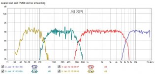
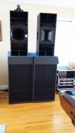
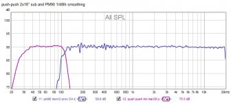
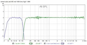
here's some plots all without smoothing, and some picts as requested.
First plot is same 4-way posted before, with smoothing removed.
It goes with the top right hand speaker on pict that follows, but with a smaller single 18" sealed sub, not the subs shown in pict. Top is the PM90, a 3-way box known on the forum.
2nd plot is a recent redo of same speaker on a double 18" push-push reflex sub. But without separate plots of the top's three passbands.
Like said in previous post, I quit keeping individual sections after processing because I knew the drivers would work together.
As an aside, I was happy to see how me tuning on the same top has improved a bit over the years.
3rd plot is a modular system using a single 12" in its own box, and a coax CD in its own box, on top of as single 18" vented sub. It's what's in the second pict minus the smaller sealed sub sitting on the vented sub. I have a double 12" modular mid that plots the same.
A big part of the logic behind the crossover method I've been proposing is that it allows easy experimentation and interchange of different drivers, horns, boxes, and subs.
It's easily achievable because once all the drivers' flattening is accomplished, complementary crossovers can be moved around at will without any need to re-tune the drivers.
Attachments

Off topic
Hi Mark,
I spotted a Rosetta in the pic, you use them rather than the converters inside your amps? How do you implement your filtering within your signal path then?
Your method regarding filter is the way it is done in PA for years. And i'm like you about the 'conventional' approach to passive filtering, this always confuse me. And i have great respect for those mastering this art!
Last edited:
Off topic
Hi Mark,
I spotted a Rosetta in the pic, you use them rather than the converters inside your amps? How do you implement your filtering within your signal path then?
Your method regarding filter is the way it is done in PA for years. And i'm like you about the 'conventional' approach to passive filtering, this always confuse me. And i have great respect for those mastering this art!
Hi Krivium, it's a psx-100. I got it when i was having trouble routing multiple aes channels into a few minidsp opendrcs.
Nowadays, I've gone entirely to qsc's Q-SYS for filtering/routing/control. All over ethernet. Converters are in the qsc amps, or in a q-sys I/O frame if feeding pure analog amps.
I truly share your great respect for all who have mastered the passive art !!!
here's some plots all without smoothing, and some picts as requested.
Very nice, thank you. What is is to be a single man!
How do you get the bass response plots? Do you drag all your gear outside for free field measurement?
Very nice, thank you. What is is to be a single man!
How do you get the bass response plots? Do you drag all your gear outside for free field measurement?
Thx ! and Lol...I guess my room screams single 😉
But truth is, I have a wonderful girlfriend...who gets her own house space too, for her to muck up.
(After countless years of marriage, I learned what to look for in a partner, and what kind of deal to make 😀)
Yes re measurements... for subs I go out on the driveway in front yard.
For tops I measure off a deck off the back of house, unless it's a critical measurement, then out front too.
Subs are easy, done once, done forever. Tops will always be a pursuit i guess...
- Home
- Loudspeakers
- Multi-Way
- Phase and time delay