You're the one telling the story, maybe you should be the one to verify the benefits/limitations?
Let's be clear about this.
Closed box, also known as Infinite Baffle, just delivers better timing than reflex.
TBH, I am more excited about tomorrow's Rugby fixture with Australia.
England v Australia: Ex-team-mates Eddie Jones & Michael Cheika go head-to-head - BBC Sport
We Britishers just feel confident that we have more than you Aussies. TBH, you were pushed over by Wales. And we can beat Wales any day of the week!
You're the one telling the story, maybe you should be the one to verify the benefits/limitations?
Ok, I get it, the original question was for only a 1kHz pulse. I may have weaved a complete speaker into the story, but as it turned out, the thread opener wasn't aware of the basics. But in the end he created a good phase match between their drivers combined with a flat frequency response, and then I can't really tell how good it is for him or anyone else.
I just thought he wanted to do something like that. Let's ask him.
AllenB says it again! This phase vs. delay thing is difficult to understand.
Now we must remember what the crossover does - it changes the response and relative phase or a driver - but low-pass and high-pass counteract! With symmetric Bessel or LR crossovers, they simply said meet eatch other and sum nicely way past xo nominal frequency. As result, the phase of summed response gently slides to make that ½ or full rotation. This applies when acoustical centers are aligned, which they almost never exactly are. With dsp this correction is typically about 0.05ms.1ms delay setting is nonsense.
Below a first order xo with 90¤ shift
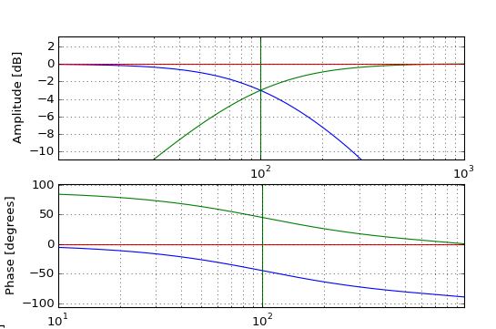
Time Alignment Part Three: Delays and Crossovers for Tweeters and Mids – Tech Tips – Forums
Phase, Time and Distortion in Loudspeakers
Now we must remember what the crossover does - it changes the response and relative phase or a driver - but low-pass and high-pass counteract! With symmetric Bessel or LR crossovers, they simply said meet eatch other and sum nicely way past xo nominal frequency. As result, the phase of summed response gently slides to make that ½ or full rotation. This applies when acoustical centers are aligned, which they almost never exactly are. With dsp this correction is typically about 0.05ms.1ms delay setting is nonsense.
Below a first order xo with 90¤ shift
Time Alignment Part Three: Delays and Crossovers for Tweeters and Mids – Tech Tips – Forums
Phase, Time and Distortion in Loudspeakers
Last edited:
Ok, I get it, the original question was for only a 1kHz pulse. I may have weaved a complete speaker into the story, but as it turned out, the thread opener wasn't aware of the basics. But in the end he created a good phase match between their drivers combined with a flat frequency response, and then I can't really tell how good it is for him or anyone else.
I just thought he wanted to do something like that. Let's ask him.
My original post used 1 kHz as a convenient number around which I could frame my question. The scenario was completely hypothetical - it was just convenient that at 1 khz the period is 1 millisecond. My question was essentially whether an LR4 phase delay (if that's the right way of putting it) of one period actually delays the sound by 1 ms (at that frequency). The broader implication of this was that if my DSP time delays were off by a long way, I could be smearing the sound.
I have learned quite a lot from this discussion, but I freely admit that there's an enormous amount that I will never grasp. This is the main reason why I have chosen the DSP route instead of grappling with the intellectual challenges of passive crossovers. I have been a member of diyAudio for many years, but have never posted. The main reason for this is that you guys are way over my head most of the time!
YSDR, I very much appreciate all your efforts on my behalf. In your post earlier today you said, almost as an aside: "the deep, wide reverse null shows to me that the drivers are phase aligned". I was slowly and painfully coming to that conclusion myself, so that statement alone was worth its weight in gold. I hope that others may have picked up some useful information along the way as well, without testing tempers and patience too much.
This phase vs. delay thing is difficult to understand.
With dsp this correction is typically about 0.05ms.1ms delay setting is nonsense.
Ain't that the truth!
Juhazi, good to hear from you. I still refer to the "systemised approach" you gave me at the beginning of this year on a different forum.
The acoustic centre delay for my tweeter is about 0.07 milliseconds (the mid and woofer are almost identical), yet I had to use delays of 0.40 ms on the mid and 0.47 on the tweet to get the deep nulls. It was these numbers that got me thinking about LR4 phase delays.
With dsp one should eq each driver to give flat acoustic response before setting xo slopes. If you are a master and combine natural low-end roll-off without eq, you can't use the preset "ideal" xo slopes that eg. minidsp or Hypex have.
An easy way to test phase/response match is the "reverse polarity test", with LR2 then set same polarity of wires.
Another way is to look at step response of the system, impulse peaks should follow and combine typically and without hickups. This takes more routine to understand.
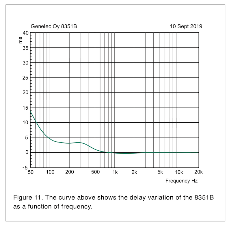
A two- or multiway speaker without FIR tricks always has certain group delay "profile", depending on what kind of xo slopes are set and at which frequency. Getting a clean reflection-free measurement is essential to analyze a GD. This is given by Genelec for a 3-way 8351B SAM™ Studio Monitor | Genelec.com. It is a 3-way and notice that M-T delay is so small that you can't read it! W-M xo is around 400Hz and has almost 3ms GD, (obviously LR4). The upwards curve below 100Hz is because of the deep roll-off/high-pass of the reflex-tuned woofer and high-pass filtering that protects the woofer from over-excursion below tuning frequency.
An easy way to test phase/response match is the "reverse polarity test", with LR2 then set same polarity of wires.
Another way is to look at step response of the system, impulse peaks should follow and combine typically and without hickups. This takes more routine to understand.
A two- or multiway speaker without FIR tricks always has certain group delay "profile", depending on what kind of xo slopes are set and at which frequency. Getting a clean reflection-free measurement is essential to analyze a GD. This is given by Genelec for a 3-way 8351B SAM™ Studio Monitor | Genelec.com. It is a 3-way and notice that M-T delay is so small that you can't read it! W-M xo is around 400Hz and has almost 3ms GD, (obviously LR4). The upwards curve below 100Hz is because of the deep roll-off/high-pass of the reflex-tuned woofer and high-pass filtering that protects the woofer from over-excursion below tuning frequency.
Last edited:
Another good read! The author states: "In a 4th order LR alignment, the speakers are at -6dB at the crossover and the shape of the rolloff has been changed (Q is 0.5 instead of 0.707)". I hadn't associated the shape of the roll-off with Q. I'm not sure yet how useful this knowledge is, but it's another small step.
With dsp one should eq each driver to give flat acoustic response before setting xo slopes.
It is a 3-way and notice that M-T delay is so small that you can't read it! W-M xo is around 400Hz and has almost 3ms GD, (obviously LR4).
DSP: this is what YSDR suggested. It was certainly easier than trying to take all the lumps and bumps out of a combined response.
3ms GD: this is reassuring, because it's of the same order as the delays I've been using.
My sincere thanks to everyone who has contributed to this thread. I am no longer worrying about whether my delays are incorrect, and I've learned a lot of useful stuff along the way!
M
M
Q defines the shape of the roll off 🙂 Welcome to the wonderful (confusing) world of filters....etc.....
Group delay has a different audibility threshold at different frequencies, have a look at that section in Rod's article
Group delay has a different audibility threshold at different frequencies, have a look at that section in Rod's article
Last edited:
DSP: this is what YSDR suggested. It was certainly easier than trying to take all the lumps and bumps out of a combined response.
et"
You don't "set" that GD as delay in dsp! It comes as given by xo type and frequency. The delay setting of dsp is for fine-tuning of the (physical) delay offset, to get perfect summing of responses/phases of each driver.
Most likely, if you set 3ms delay to woogfer, it gets one full cycle "late" which means that summing before and after the xo point are a mess, as well the step resonse.
Many web articles about "time aligning" are for huge Pa systems that use woofers, mids, tweeters in separate boxes and with horns. There comes the rule of "aligning voice coils" which is nonsense for hifi speakers. The acoustic centers of drivers are never at coil plane!
Linkwitz-Riley Crossovers: A Primer
An externally hosted image should be here but it was not working when we last tested it.
You don't "set" that GD as delay in dsp!
Most likely, if you set 3ms delay to woofer, it gets one full cycle "late" which means that summing before and after the xo point are a mess, as well the step resonse.
Yes, I understand that I don't use that delay.
Sorry, that was a brain fart on my account...I translated 3ms into .3ms. All is well!
Perhaps when doing a limited, single measurement per driver crossover, otherwise no this doesn't make sense. This is fine if it is all that is required.. your comments misrepresent what can be done.Juhazi said:With dsp one should eq each driver to give flat acoustic response before setting xo slopes.
Not so when simulation/processing is carried out, and I contend that it should be with a full crossover. The outcome is a target for each driver.you can't use the preset "ideal" xo slopes that eg. minidsp or Hypex have.
Last edited:
Now that we have gotten there - I don't understand the need for textbook filter slopes, unless you are using active X/O with set orders/slopes. I just use whatever sums well and keeps the tweeter out of trouble. While I still tend to think in terms of the classic filter shapes, my crossovers rarely end up that way. Neither electrical nor acoustic.
Ok, my 2 cents..but with regards to xovers in general...not going into the phase quagmire 🙂
When it's said and done, ALL crossovers, whether passive or active, whether textbook sloped / named crossovers or not,........ end up being complementary acoustic crossovers...and as such end up being identical electrically if properly constructed to achieve a given acoustical order..
By complementary acoustic crossover, I mean in-phase at every frequency, and magnitude sums to zero (letting zero =flat).
This has to be, or the crossover did not do its job properly.
And for a given complementary acoustic crossover, electrical crossover has only one solution....which is the same solution no matter how arrived.
All on board still?
Ok, If the electrical xovers have to end up being identical to achieve a given complementary acoustic crossover, what's the easiest way to achieve the electrical xover...???
One way is to juggle...the common way...add whatever electrical xover to the natural rolloff/response of each driver until you finally hit a complementary summation ...a lot of trial and error, a lot of art, and needed experience.
Another, much better way imo, is to flatten the response of the driver out of band electrically, boosting its response to flat throughout the intended crossover region, knowing that it is only a temporary adjustment that will be offset with xover.
Then, apply a complementary textbook xover at the order you wish, and guess what?
You just very simply reached the exact same electrical xovers you would have eventually achieved with juggling !!!
The out of band flattening and complementary textbook crossover = proper juggling.
It's an identity.
And even if you want asymmetric crossover orders above vs below xover freq, you can still do that by summing symmetric high or low cut filters to both drivers on the side you want to alter.
Which method is easier and more straightforward? To me, it's a no brainer..
Plus there are no time alignment issues with the flatten out-of-band, add complementary xover approach. Time alignment just comes down to time-of-flight to drivers.
And again, passive vs active, IIR vs FIR...all immaterial.
It's the logic of the xover tuning process, imho.
Hope this all was clear / made sense.
Now that we have gotten there - I don't understand the need for textbook filter slopes, unless you are using active X/O with set orders/slopes. I just use whatever sums well and keeps the tweeter out of trouble. While I still tend to think in terms of the classic filter shapes, my crossovers rarely end up that way. Neither electrical nor acoustic.
A big advantage I see about textbook acoustical LR slopes is that they do not causes peaks on-axis and off-axis (at least from the crossover point of view) in the frequency response because the maximal gain from two or more drivers occours at on-axis which will sums flat in the frequency domain and in a good case, this is the axis with the highest sound pressure.
mark100 - we have other types os crossovers that are not symmetrical, eg. Harsh. Sometimes non-perfect phase match at design axle is intentional, eg. o get better off-axis dispersion or to tilt the nulling lobe as desired.
AllenB - yes I was simplifying this. Off-axis dispersion must be investigated and and xo selection should be and educated compromise between on- and off-axial response and distortion (we dont want to stress the high-passed driver too much) etc. modern design criteria.
Pano - acoustic response, spl and phase is what we should look at. Many articles of xo focus on electrical "textbook" circuit mathematics and theoretically imply flat acoustic spl response of drivers to work IRL. But real life is more painful!
Last edited:
Thanks for that image of a typical loudspeakers time response, Juhazi:
I was struggling to find that one in the archive, but it makes sense. The extreme time delay in the low bass due to steep rolloff below 100Hz. A little s-shaped curve in delay maybe due to bafflestep from 100-500Hz and certainly the filter itself. The top end comes though undelayed, because high-pass becomes instant at high frequency.
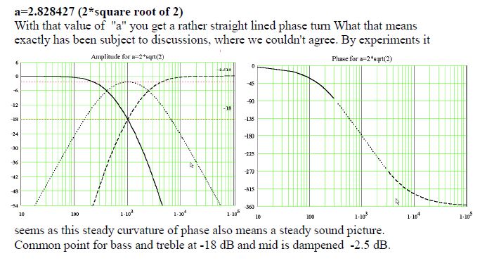
This is how the maths works out for most classic filters:
Two-way:
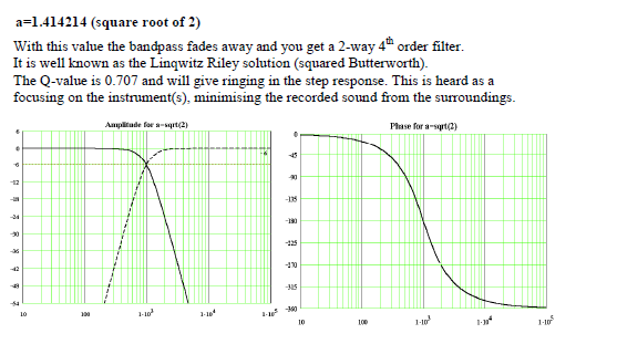
Three-way:
Here's a fun exercise for you:
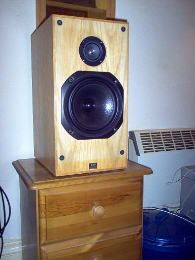
A closed box monitor with a cone tweeter:
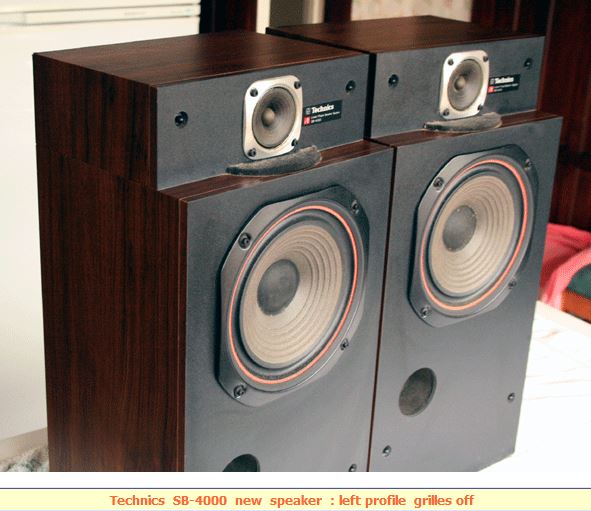
And something not wildly different except reflex and time aligned:
I think both probably work well enough. We'll take our beating on the narrow dispersion of a cone tweeter. All is compromise. 😀
I was struggling to find that one in the archive, but it makes sense. The extreme time delay in the low bass due to steep rolloff below 100Hz. A little s-shaped curve in delay maybe due to bafflestep from 100-500Hz and certainly the filter itself. The top end comes though undelayed, because high-pass becomes instant at high frequency.
This is how the maths works out for most classic filters:
Two-way:
Three-way:
Here's a fun exercise for you:
A closed box monitor with a cone tweeter:
And something not wildly different except reflex and time aligned:
I think both probably work well enough. We'll take our beating on the narrow dispersion of a cone tweeter. All is compromise. 😀
Last edited:
mark100 - we have other types os crossovers that are not symmetrical, eg. Harsh. Sometimes non-perfect phase match at design axle is intentional, eg. o get better off-axis dispersion or to tilt the nulling lobe as desired.
Yes Juhazi thx, I've seen how some use crossovers to control/alter lobing patterns in the crossover region.
I guess that can be useful sometimes when a speaker can't be tilted, or the listening environment really benefits from an non-symmetrical pattern. Are there other similar cases you are aware of?
At any rate, it's only the crossover region that can be controlled, so it's hard for me to see why simple delay couldn't be used in a much more straightforward way of controlling the lobing, than more complicated xovers.
That's where I'm coming from really....I just don't get why we make crossovers so dang complicated, when there is such a straightforward manner to build them.
But then again, my method assumes/requires a good number of IIR eqs per driver, and realistically, a willingness to go active multi-amp. Which ain't full reality....
I think even if I did want to stay passive, I would find the passive "juggle result" I want to build (for lack of a better term), by using active out-of-band flattening, then adding in the crossover method per my previous post.....and use that summed electrical curve as what I need to replicate passively, if possible.
I can also see another case where we would want an asymmetric order around crossover. If after applying out of band flattening and the desired symmetric order xover, one side of the band on one driver shows too much net boost, or insufficient attenuation for safe excursion, it's saying we need a higher order xover for that driver on that side. But maybe we like the summation/order on the other side. So then I can see wanting to add additional complementing filters to change order on just one side. But they could easily be filters such as shelving without needing more xover complication.
99% of the time I simply have trouble understanding why we make crossovers such a complicated topic. I guess if a I go beyond a KISS xover method, i turn into a complete dummy. Especially when the KISS method appears to be the easiest and most accurate 🙂
- Home
- Loudspeakers
- Multi-Way
- Phase and time delay