Sorry, Christian, I'm not following you. I am vaguely aware of the process for measuring TS parameters but have never tried it myself.So a ratio of impedance of 0,74 and 0,98...? What's wrong?
I wondered about that too. The aluminum peaks are so sharp. Are those numbers any good? And how sensitive might the results be to the FFT parameters? I didn't really give them any thought, I just used the parameters I usually use when I'm trying to estimate elastic properties, and for that only the frequency mattters, not the shape of the curve. But I'm really not sure I care about the real Q of aluminum, anyway.With the value of Q you shown for aluminum, I wonder if we have the required precision in frequency but mainly I have the feeling there is a limit due to the exciter damping. Could we really observe very high Q when the exciter brings its own damping?
But the PMMA and EPS are much more like materials I think I might actually use. And I thought it was interesting that the Qs I derived from the tap test for those seem virtually unaffected by the addition of the exciter. It's too soon to generalize but I'm wondering now if the exciter Q really plays a big role or not. How should Qs add? Like resistors in parallel? With some kind of weighting that depends on mass or stiffness or the like? Other?
Eric
Dave, that makes sense. So acoustic loading is in your model then? Probably you said so before, but I forgot. It's often negleted, right?Here are the results with the point force. It does increase up to a point, then losses from acoustic loading take over. So it can't keep going forever!
Out of curiosity, what were the E and rho values in the most extreme case you showed?
Eric
Still no power but online via mobile and generator... Expected fix tomorrow 9pm.
In the meantime I'm wondering about smoothing... If all these Q figures are so high then the fr graphs will look horrendous, and it makes the task of getting an acceptable panel response look rather hopeless.
@EarthTonesElectronics
Hi Dave;
1/Are the fr graphs in PETTaLS raw, ie no smoothing?
2/ If so, can we get a smoothed response ?
3/ If not, can we get a text output to better fiddle with?
And in terms of damping, should we be examining the effect of broadly applied material like lightweight self adhesive felt to the rear of panels?
Regards
Eucy
This sounds right to me.For the tap tests, I used the points 3dB below each peak SPL to determine the bandwidth for the Q calculation. For the impedance test, I use the points at 70.7% of the peak, referenced to the impedance curve baseline in the vicinity of the peak. I'm still not sure if these are the "correct" calculations.
So that was really 9.5mm thick aluminum? I can imagine that having very high Q values.The aluminum peaks are so sharp. Are those numbers any good?
Both - like resistors in parallel, but with a weighting that depends on how close the resonances are to each other and how much relative velocity they each have. The actual relationship is probably even more complicated than that!How should Qs add? Like resistors in parallel? With some kind of weighting that depends on mass or stiffness or the like? Other?
Yes, I put in a simple version of acoustic loading (e.g. purely resistive). It is often neglected, but it's apparently somewhat impactful here at low frequencies and especially when the density of the panel is very light.Dave, that makes sense. So acoustic loading is in your model then? Probably you said so before, but I forgot. It's often negleted, right?
Out of curiosity, what were the E and rho values in the most extreme case you showed?
Eric
1. Yep, no smoothing applied.1/Are the fr graphs in PETTaLS raw, ie no smoothing?
2/ If so, can we get a smoothed response ?
3/ If not, can we get a text output to better fiddle with?
2. I can add in a dropdown for smoothing eventually. I've always been a little bit skeptical of smoothing in DMLs - most of the old NXT/Tectonic speaker datasheets always had a significant amount of smoothing applied which totally obfuscated the fact that there were significant peaks and ringing. But yes, I can always add it in, haha.
3. Yes, I can certainly do this too. Eventually!
Absolutely - after I finished my PhD, the students in my lab who were still working on speakers spent quite a lot of time characterizing adhesive damping properties. It worked really well to improve the sound of the speakers when applied properly. Not sure if any of that got published anywhere, unfortunately.And in terms of damping, should we be examining the effect of broadly applied material like lightweight self adhesive felt to the rear of panels?
A shame... More wheels to re-invent 🤷♂️Not sure if any of that got published anywhere, unfortunately.
Dave..I've always been a little bit skeptical of smoothing in DMLs - most of the old NXT/Tectonic speaker datasheets always had a significant amount of smoothing
I think that it's reasonable to the extent that:
a) it best represents the averaging effect of *human hearing and;
b) it reduces the misery of a terrible looking mathematical fr curve that I can't hear anyway 😵💫🤭
Eucy
* normal hearing... If it was based on mine it it would look like a lopsided frown ☹️
Both raw and smoothed FR are interesting in audio tools. Raw to understand or detect what happens, smoothed to have an idea of what we can hear. The problem is to know how to smooth, hearing is complex. Like in REW with 1/nth of octave and more sophisticated one (variable, ERB...)?it best represents the averaging effect of *human hearing
Christian
No sorry, it's me. I started by a digression without the proper introduction.Sorry, Christian, I'm not following you. I am vaguely aware of the process for measuring TS parameters but have never tried it myself.
Yes, aluminum is more a "test case". Clear.But the PMMA and EPS are much more like materials I think I might actually use. And I thought it was interesting that the Qs I derived from the tap test for those seem virtually unaffected by the addition of the exciter.
The fact PMMA and EPS are not affected by the exciter means the additional components (mass, stiffness, damping) from the exciter are neglectable compare to the panel one. I don't remember figures shared about that but it is more or less behind all our experiences.
For now I prefer to see the exciter has a component having mass, stiffness and damping which work along with the equivalent mass, stiffness and damping of the panel.It's too soon to generalize but I'm wondering now if the exciter Q really plays a big role or not.
Each system we consider having its final Q (exciter alone, panel alone driven by a pure force, panel with an exciter...).
I am at a step of trying to make some equivalent schematics with the mass, stiffness and damping of each. The combinaition of Q is a bit too theoric for me before going deeper.How should Qs add? Like resistors in parallel? With some kind of weighting that depends on mass or stiffness or the like? Other?
Christian
res ipsa loquitur ChristianBoth raw and smoothed FR are interesting in audio tools. Raw to understand or detect what happens, smoothed to have an idea of what we can hear. The problem is to know how to smooth, hearing is complex. Like in REW with 1/nth of octave and more sophisticated one (variable, ERB...)?
Christian
I just uploaded v1.3 of PETTaLS to the github site, along with change notes. No real major changes, but a few wrinkles have been ironed out!
I've decided to update the first decimal point whenever a change is made to the underlying model, and the second decimal point whenever the changes are simply to the UI. In this case I updated the point force model a little bit, so it's 1.3 instead of 1.2.2.
I'm planning to make more videos and try to advertise this model more widely as soon as I feel the release is pretty stable. Thanks everyone for all of the helpful suggestions so far!
All of the equations for this are essentially in my thesis, but they're pretty complicated! Eq. 7.9 is the good one that relates the modes and exciters.I am at a step of trying to make some equivalent schematics with the mass, stiffness and damping of each. The combinaition of Q is a bit too theoric for me before going deeper.
Just now I tried to derive equations for the Qs of a coupled exciter and single mode (because all of the modes actually couple to each other through the exciter and influence one another slightly), but unfortunately you end up with a 4th order polynomial that has all orders in between, and factoring this into two 2nd order polynomials with respective Q factors seems annoying. If this was still 10 years ago and I was still a PhD student with endless free time maybe I could figure it out! This is why I wrote the simulation software - the equations quickly become prohibitively long.
Your thesis is an excellent reference paper. You have probably seen in previous post that I refer to it.All of the equations for this are essentially in my thesis, but they're pretty complicated! Eq. 7.9 is the good one that relates the modes and exciters.
Yes, the equations are not "friendly".Just now I tried to derive equations for the Qs of a coupled exciter and single mode (because all of the modes actually couple to each other through the exciter and influence one another slightly), but unfortunately you end up with a 4th order polynomial that has all orders in between, and factoring this into two 2nd order polynomials with respective Q factors seems annoying. If this was still 10 years ago and I was still a PhD student with endless free time maybe I could figure it out! This is why I wrote the simulation software - the equations quickly become prohibitively long.
A way of simplification is to say that locally around the resonance of a mode, the contribution of the other modes are low enough. Are they?
Christian
Hello Eric,I made some attempts to quantify Q for three different panel materials, using both the impedance test and tap test methods. The overall results look something like this:
PMMA (Acrylic) : ~20
EPS: ~70
Aluminum: ~1000
Are these correct? Not sure, but they were pretty consistent.
Here is a link Measuring speaker element parameters about the classical method to get the parameters of a loudspeaker from the impedance measurement. A single measurement is enough to evaluate the quality factor Qms of the mechanical system (the Q we are looking for).
The added mass technique is necessary to go further to get the mass and the stiffness.
Here is the Qms evaluation on a graphical form:
I don't know the math behind but this is standard for classical cone speakers. It is what I used long time ago, before REW.
I applied it on your measurements and compared to your evaluations. See below
The PMMA seems quite constant in Q in this frequency range.
The EPS seems of an other kind.
Christian
PS: Rc is from the link, same as R0 above.
PS2: Re+Res is Rmax
Thanks Christian, that is very helpful. I'll need to take a closer look at that.Here is a link Measuring speaker element parameters about the classical method to get the parameters of a loudspeaker from the impedance measurement. A single measurement is enough to evaluate the quality factor Qms of the mechanical system (the Q we are looking for).
One minor point, regarding the lowest peaks (at 23 and 30 Hz for EPS and PMMA), I avoided those in my calculations because they are so close to the exciter's magnet resonance. But I suppose those are "valid" or not, depending on whether you are trying to measure Q of the system, or of the panel itself. I was looking at it from the perspective of the panel alone, so I was avoiding peaks that I suspected to be most strongly influenced by the Q of the exciter itself.
The aluminum result is an extreme example, but shows clearly my meaning. It would make no sense to calculate Q for the lowest peak here (34 Hz) and suggest that it reflects the Q of aluminum.
Eric
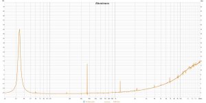
Yep. It is and it sure does. I'm not sure if 1000 is close to the true Q or not, but I think I could tap it before I went to bed and it would still be ringing in the morning!So that was really 9.5mm thick aluminum? I can imagine that having very high Q values.
Eric
I just uploaded v1.3 of PETTaLS to the github site, along with change notes. No real major changes, but a few wrinkles have been ironed out!
Dave,
I didn't load 1.3 yet, so this refers to 1.2.1. I'll load 1.3 shortly, but 1.2.1 is running so fast at the moment I hate to change anything.
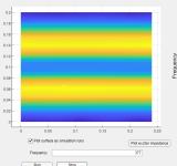
Meanwhile, I think there may be something amiss in the FFFF model. I was doing another test to compare the natural frequencies in the your simulation to those predicted by my FEA, but using the FFFF case. This time, in order to excite all (or nearly all) of the modes, I used a point force very near the corner (0.02,0.02). There was a little more difference between the two sets of predicted resonances for the FFFF case than for the SSSS case. But more importantly, some modes that should have been driven were completely missing in the Pettals simulation. There may be others missing, but the most obvious missing modes are the two below. Similar higher order modes (i.e. with five nodal lines instead of three) were also "missing" from the Pettals sim.
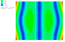
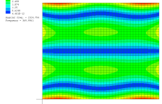
By moving the driving point to 0.33/0.33, I was able to "find" those missing modes, but they were not quite the correct mode shape. That is, the nodal lines closest to the edge are actually on the edge, rather than just inside it. So it's clear now why theses modes were not driven by the corner placement: the simulation thinks that the corner is a node for those modes, though it should not be.
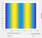
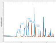
See also the impedance plots. Note that the corner placement (blue) doesn't drive the modes at 262 Hz and 377 Hz at all, though it should (if the mode shape was correct).
If you want to reproduce this test exactly, I used:
Acrylic properties, but Q=100.
0.24 x 0.20 x 0.003 panel dims.
Eric

@EarthTonesElectronics
Dave,
As you probably suspected would be the case, I found the same issue with version 1.3 regarding the funky FFFF mode shapes. Here's another one (same model parameters).
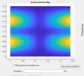
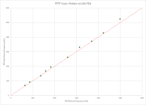
Here also is the comparison of the FFFF modal frequencies for FEA compared to Pettals. They are not as close as in the case of SSSS. For SSSS the greatest disparity I saw was under 2%. For FFFF it is as much as about 6%. The greatest disparity is in the lowest modes, where 5 of the 7 lowest modes are about 5 to 7% higher frequency in Pettals compared to the FEA. I don't have a guess as to the reason for that. I think it is independent of the mode shape issue, since the two lowest "funky" modes occur at 262 and 272 Hz, where the agreement between the two models is actually very close.
Eric
Dave,
As you probably suspected would be the case, I found the same issue with version 1.3 regarding the funky FFFF mode shapes. Here's another one (same model parameters).

Here also is the comparison of the FFFF modal frequencies for FEA compared to Pettals. They are not as close as in the case of SSSS. For SSSS the greatest disparity I saw was under 2%. For FFFF it is as much as about 6%. The greatest disparity is in the lowest modes, where 5 of the 7 lowest modes are about 5 to 7% higher frequency in Pettals compared to the FEA. I don't have a guess as to the reason for that. I think it is independent of the mode shape issue, since the two lowest "funky" modes occur at 262 and 272 Hz, where the agreement between the two models is actually very close.
Eric

@EarthTonesElectronics
Free square plates have some fun mode shapes that are sensitive to the Poisson's ratio, so I ws going to look at that too. But before I really got to that, I found this other funky mode shape (using the same panel as before but 0.24 x 0.24 m size). But I'm pretty sure this shape violates conservation of momentum,
I think I'll stop disparaging your FFFF model now (sorry).
Eric
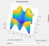

Oh good lord - I think the issue was just an errant minus sign in the code. (There's a lot of code, in my defense!)@EarthTonesElectronics
Dave,
As you probably suspected would be the case, I found the same issue with version 1.3 regarding the funky FFFF mode shapes. Here's another one (same model parameters).
View attachment 1434269
Here also is the comparison of the FFFF modal frequencies for FEA compared to Pettals. They are not as close as in the case of SSSS. For SSSS the greatest disparity I saw was under 2%. For FFFF it is as much as about 6%. The greatest disparity is in the lowest modes, where 5 of the 7 lowest modes are about 5 to 7% higher frequency in Pettals compared to the FEA. I don't have a guess as to the reason for that. I think it is independent of the mode shape issue, since the two lowest "funky" modes occur at 262 and 272 Hz, where the agreement between the two models is actually very close.
Eric
View attachment 1434272
Using your simulation parameters, here's a new 262 Hz shape:
Here's 377 Hz:
Here's the new impedance:
You're right that this issue was totally independent of the resonant frequencies. It's unlikely that this issue will have any effect on the coupled resonances since it was done with a point force, but there could be a tiny effect.
I don't see any issues with the frequency calculations - it could just be that the analytical expressions are less accurate for the free edges than for the clamped or simply supported edges, but I'll keep looking into it.
- Home
- Loudspeakers
- Full Range
- PETTaLS Flat Panel Speaker Simulation Software