Dear Shaan, nice work PCB V1.1 and V2!
But I cannot understand, why have You done 2 "ground loops" in V1.1 (two separate traces per supply - from supply decoupling caps to star GND point). In theory - it is not good.
For example - loops in PCB's:
Audiophile Musings: What the HECK is a Ground Loop
http://1.bp.blogspot.com/-P0mFFVtDGmQ/UWgFy3lGFgI/AAAAAAAAAeg/XFFBvT_5eMA/s1600/Ground+Loop+4.jpg
Despite that - performance (graphs, test results) are very good 🙂
Last edited:
Hello Guitar.mod 
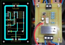
These two loops resulted from my unstoppable urge to keep the effective thickness of the decouple ground traces as high as possible within that small board 😀 (even smaller than v1 and holding more components than that as well). These loops have only decoupling capacitor's charging current flowing through them and contains no signal current. Although they are indeed loops that are made by, well, dropping a loop in each trace, they are not (and won't act as) what we know as "ground loop" which indicates a closed conduction path between two systems' grounds causing noise current to flow through signal line's sheild conductor causing motorboating and other noises. Within each loop and between them this is simply impossible to happen. 😉
Thanks for the kind words. 🙂
Edit😛s: these loops won't "Smear" the sound. 😀
Last edited:
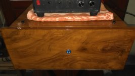
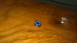
Beautiful case. Teak is a nice wood. Where is everyone getting these blue ring power on/off switches from? I have seen them popping up on a lot of builds.
Hi fellas.
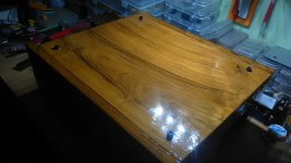
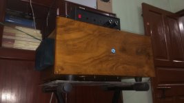
The v2 monster has been born, with a teak body. 😀
Hi Shaan,
Amazing work on the case. Nice shine, I envy.
X the switches are led 5A switches like this one here.
LED Power Logo Switch -Blue_Latching
Description might help you to locate on your favorite store, the Ali-(slow boat from china)-express😀... just kidding...
Nice enclosure shaan!!Hi fellas.
The v2 monster has been born, with a teak body. 😀
Sent from my GT-N7100 using Tapatalk
Thanks Prasi. This looks like it but need a free shipping version.
The circle logo less common than I/o logo.
YOCOMYLY (TM)QN 16mm Blue 12V Circle LED Latching On/Off Push Button Switch & 5 pin socket plug-in Switches from Home Improvement on Aliexpress.com | Alibaba Group
YOCOMYLY (TM)QN 16mm Blue 12V Circle LED Latching On/Off Push Button Switch & 5 pin socket plug
@xrk971
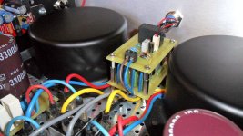
These switches are plain contact type. You will need a latch circuit with relay for switching on the power. I built one on veroboard and used in this amp.
These switches are plain contact type. You will need a latch circuit with relay for switching on the power. I built one on veroboard and used in this amp.
In several projects I used a small assembly which provides power to the limineux circle with a light adjustment directly on the sector and which also allows the sector to bring the following items.@xrk971
These switches are plain contact type. You will need a latch circuit with relay for switching on the power. I built one on veroboard and used in this amp.
The operation is flawless and even in a preamplifier RIAA no noise problems.
🙂
Attachments

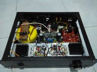
Hi guzz. I can see only the CM power supply. Where is peeceebee? More photos please. 🙂
tidying up messy cables in progress 😀
Nice diy there! 
I like how those two black heatsinks are mounted. Good execution, better dissipation.
Congrats!
I like how those two black heatsinks are mounted. Good execution, better dissipation.
Congrats!
Thank Shaan, Found that black heatsink from old CPU cooler, cut in to two pieces then mount it there. The torodial transformer was 18-0VAC dual secondary, modified to 24.5VAC CT (extend couples turns of enamel wire), it was 6.25A for single rail based on the datasheet, should be enough to supply peeceebee. 🙂
Hi guzz,
I Like Your Idea to fasten contact bricks on the toroidal transformer via wooden plate!
It looks not vey nice, but it is very practical ! 🙂
I Like Your Idea to fasten contact bricks on the toroidal transformer via wooden plate!
It looks not vey nice, but it is very practical ! 🙂
At the MacGyver!Hi guzz,
I Like Your Idea to fasten contact bricks on the toroidal transformer via wooden plate!
It looks not vey nice, but it is very practical ! 🙂
- Home
- Amplifiers
- Solid State
- PeeCeeBee