Ok i will measure the diode this afternoon. What is the voltage should read across that one?
Between 600mV and 800mV.
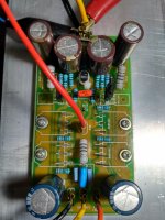
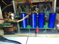
AwesomeHad been having a hard time with time. One of the boards gets populated, ready to be tortured.
Looks good eh? 🙂

Between 600mV and 800mV.
I did not say it sings bad, it sings very good, but with higher bias maybe it will sing more pleasant.
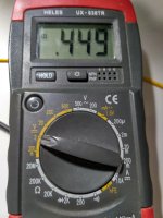
Measurement I conducted last night. 449mV across diode 4148
Best Regards.
Attachments
I did not say it sings bad, it sings very good, but with higher bias maybe it will sing more pleasant.
Measurement I conducted last night. 449mV across diode 4148
Best Regards.
This voltage indicates less than 0.1mA bias in VAS section, which is too low.
Check the voltage around two 10R/1W resistors near the VAS transistors. Measured voltage should be 100mV for 10mA VAS bias. You will need to turn the two trimmers to get the VAS bias to 10mA. If bias don't get near 10mA even after turning the two trimmers to zero resistance then turn them back to maximum resistance and change the two 27K resistors to the next lower standard value i.e. 22K and then check the two 10R/1W resistors for voltage drop again.
With proper VAS bias the amplifier will sound pleasing even with 30mA MOSFET bias.
All the best.
thank you so much for your advice Shaan..highly appreciated...
Best Regards
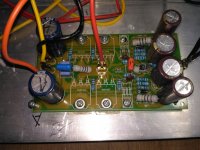
My VSSSA has 80mV across 10R/1W... my mistake, I put 33K resistors at previous. I replaced the 33K resistors with 27K. The mje’s now are installed bellow pcb because they are getting hot at 80mV. Heat sinks are a little bit warm.
I will try to set bias into 100mV later. Is it possible to rise bias more than standard and what is the advantage?
Very nice sound!!
Thank you so much Shaan.
Best Regards
I will try to set bias into 100mV later. Is it possible to rise bias more than standard and what is the advantage?
Very nice sound!!
Thank you so much Shaan.
Best Regards
Attachments
In simple terms, A higher VAS bias keeps THD low by allowing the MOSFET gates charge/discharge fast. 10mA-15mA is sufficient for these MOSFETs.
Very nice sound eh? Of course! 🙂 Congrats on a successful build. I also notice you changed the miller capacitors to something better than before. Wise step forward.

Very nice sound eh? Of course! 🙂 Congrats on a successful build. I also notice you changed the miller capacitors to something better than before. Wise step forward.
In simple terms, A higher VAS bias keeps THD low by allowing the MOSFET gates charge/discharge fast. 10mA-15mA is sufficient for these MOSFETs.
Very nice sound eh? Of course! 🙂 Congrats on a successful build. I also notice you changed the miller capacitors to something better than before. Wise step forward.
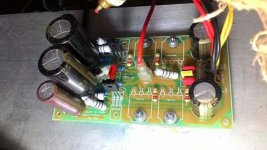
The previous one, with 32Vac. Regulated PSU..
Attachments
hi, sorry for the random and possibly old question but whats the function of 10uf cap bypassing the vias zeners?
hi, sorry for the random and possibly old question but whats the function of 10uf cap bypassing the vias zeners?
It attempts to make the bias network invisible to the VAS transistors at high frequency, improving speed. At audio frequencies I doubt there is much for it to do, however.
You can use a smaller capacitor like 1uF or even 0.1uF without problem.
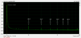
Today I did the first spectrum analysis of the new V4 PCBs.
This wasn't to happen until I got a 1KHz sine source which had extremely low THD. Yesterday the diy signal source was finished and measured 0.002%. Finally a low distortion reference for the new boards.
All got plugged in today and I took some measurements at 10WRMS (9VRMS) into 8ohm resistive load.
Total harmonic distortion is about 0.0014% (measured THD minus source THD). Well that is a very good looking number I know but the distribution of harmonic levels is what seemed interesting to me. If anything, this time H2 seems dominant.
Off to test 1W and 55W levels.
Attachments
Today I did the first spectrum analysis of the new V4 PCBs.
This wasn't to happen until I got a 1KHz sine source which had extremely low THD. Yesterday the diy signal source was finished and measured 0.002%. Finally a low distortion reference for the new boards.
All got plugged in today and I took some measurements at 10WRMS (9VRMS) into 8ohm resistive load.
Total harmonic distortion is about 0.0014% (measured THD minus source THD). Well that is a very good looking number I know but the distribution of harmonic levels is what seemed interesting to me. If anything, this time H2 seems dominant.
Off to test 1W and 55W levels.
great news. how about imd ? and thd at higher frequency like 10k or 7k
Today I did the first spectrum analysis of the new V4 PCBs.
This wasn't to happen until I got a 1KHz sine source which had extremely low THD. Yesterday the diy signal source was finished and measured 0.002%. Finally a low distortion reference for the new boards.
All got plugged in today and I took some measurements at 10WRMS (9VRMS) into 8ohm resistive load.
Total harmonic distortion is about 0.0014% (measured THD minus source THD). Well that is a very good looking number I know but the distribution of harmonic levels is what seemed interesting to me. If anything, this time H2 seems dominant.
Off to test 1W and 55W levels.
Hi shaan , does not know much about measurements but mr linkwitz publishes different method and advocates IM distortion - "Harmonic distortion products are below 0.01% for the three amplifiers measured. But musical signals are rarely single sinusoids. Intermodulation distortions are always higher than harmonic distortions and their spectral distribution is in my opinion a better differentiator between amplifiers than a single harmonic distortion number"
This is his Quote from one of his page and obviously i donot understand fully but he measures with mixed 1khz and 5. 5 kHz sine wave fluctuating at 4.5 khz at 1w and 500mw levels in to 8 ohm load, and last amplifier he has measured was ncore module (class d by burno putzeys)based from ATI and he has said the best amplifier he has measured till date
Do know merits of it but mr linkwitz is whiz
If possible measure IM distortion too
Below is the link to the page iam referring ,forgive any stupidity
LX521 Supplies
I'd love to see how V3 or V4 deals with these IMD tests.
It is interesting to see IMD but I wonder if an amplifier using fast transistors, having a good GBW product and good THD profile from 20Hz to 20KHz could have bad IMD performance at the same time....
Also what level of IMD is considered not acceptable...
Fab
Also what level of IMD is considered not acceptable...
Fab
Last edited:
Thanks drgnanam
Ok, addition made:
It is interesting to see IMD but I wonder if an amplifier using fast transistors, having a good GBW product and good THD profile from 20Hz to 20KHz at low power could have bad IMD performance at the same time....
Also what level of IMD is considered not acceptable...
Fab
Ok, addition made:
It is interesting to see IMD but I wonder if an amplifier using fast transistors, having a good GBW product and good THD profile from 20Hz to 20KHz at low power could have bad IMD performance at the same time....
Also what level of IMD is considered not acceptable...
Fab
Last edited:
Keep it below threshold of hearing, there is equal phono graph for various frequency in the page
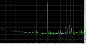
I did run this imd test against my test p3a -
1k and 5.5k at -8db it gave a 5vpp signal @ 4ohms
two tests 50ma and 1 amp biasing.
1k and 5.5k at -8db it gave a 5vpp signal @ 4ohms
two tests 50ma and 1 amp biasing.
Attachments
Last edited:
- Home
- Amplifiers
- Solid State
- PeeCeeBee