So far the veroboard prototype showed better bass, better thermal performance, better bias stability, better clipping performance, higher slew-rate, lower THD and higher gain allowance.
🙂
Thanks. V4 looks a very different amp. much more parts.
does V4 will still use the same drivers?
another comment why MJE are prefered over BD139/140 ?
I'm finding BDs easier to match than the MJE.
Thanks
Thanks. V4 looks a very different amp. much more parts.
does V4 will still use the same drivers?
another comment why MJE are prefered over BD139/140 ?
I'm finding BDs easier to match than the MJE.
Thanks
V4 came to be a different amp from the vanilla PeeCeeBee. Yes, more parts.
Yes V4 can use the same drivers (VAS). It can use any driver with TO126/TO225 package.
I prefer MJEs for the same reason you find BDs more approachable, ease of matching (and also higher average gain).
If the hFE of all the BDs made in India were put on a paper as dots, it would look like the Seismograph plot of a magnitude-9 earthquake. 😛
Nice pcb
🙂
Any chance for v4 with 2pair latfet ?
Not yet.
We're hot! 🙂
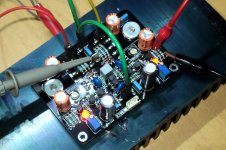
PeeCeeBee V4 PCB powered-up and running! 🙂
Some initial data,
NPN small signal BJT average hFE: 300
PNP small signal BJT average hFE: 350
NPN VAS BJT hFE: 180
PNP VAS BJT hFE: 150
Matching = Non-existent. 😀
The miller caps are double of the required value. I don't like it but I haven't any 47pF left! Time to order a box. Btw, no clicks no pops no noise no hum no oscillation. Input BJT pair not thermally coupled. Zobel resistor(s) cold.
Offset at cold-start with both trimmers set to 700ohm: -55mV (trimmed to +2mV)
Cold phase offset: +2mV
Warm phase offset: +6mV
Cold phase VAS bias: 9.9mA
Warm phase VAS bias: 10.1mA
Attachments
Last edited:
Update on the "black-beauty" V4! 😀
Okay the amp has been on for ~24 hours either playing or just chilling without any electrical or thermal issue so far. That's a good sign.
I was experimenting with the VAS current limiter transistors and found that while the two small signal BJTs perfectly limit VAS current to a very safe 16mA (47R VAS emitter resistors), they cause some problem if they are left "active" during playback. The problem they cause is a huge decrease in slew-rate; in the order of 2-3V/uS!!!
The solution is simple and easy - turning off the limiters after the amplifier has been fully set-up and ready to play music. For this, a pair of single-position DIP switches that short the base-emitter pins of the limiters will be added to the final V4 PCB.
The switches would be set to "open" when first-time setting up the amplifier, letting the limiters monitor VAS bias. After trimming VAS bias and offset, the switches would be "closed" to turn off the limiters and let the amplifier work with its highest slew-rate. Bias increase in VAS due to limiters turning off is about 100uA-150uA which is no problem. Offset will also change a few millivolts but can be safely trimmed back to zero without any chance of VAS over-current.
🙂
Last edited:
Member
Joined 2009
Paid Member
I don't think this is the right place to talk about the F5. but essentially I decided to not go ahead with my F5 because it isn't very flexible. it has very high demands on Heatsinks.
psu, specific voltage on the transformers. and I wasn't able to notice a big improvement over
my p3a, actually the p3a looks like it has more control over the speakers.
So now I want check out the PeeCeeBee, because is a very simple amplifier, looks more stable than a P3A, has similar performance, no exotic parts.
Just thought you would like to know of another alternative, beats out the P3a, but is not a beginners amp.
http://www.diyaudio.com/forums/solid-state/245619-tgm8-amplifier-based-rod-elliot-p3a.html
does V4 will still use the same drivers?
...
I'm finding BDs easier to match than the MJE.
Incidentally I am using a BD pair on the V4 PCB! They seem to work absolutely fine. And as mentioned previously they aren't matched closely.
Edit: today I will try to play the V4 alongside the old and faithful V3 and will update about the sonics in the evening. 🙂
Last edited:
Just thought you would like to know of another alternative, beats out the P3a, but is not a beginners amp.
http://www.diyaudio.com/forums/solid-state/245619-tgm8-amplifier-based-rod-elliot-p3a.html
Thanks
The switches would be set to "open" when first-time setting up the amplifier, letting the limiters monitor VAS bias. After trimming VAS bias and offset, the switches would be "closed" to turn off the limiters and let the amplifier work with its highest slew-rate. Bias increase in VAS due to limiters turning off is about 100uA-150uA which is no problem. Offset will also change a few millivolts but can be safely trimmed back to zero without any chance of VAS over-current.
🙂
Why keep the those current limiter if they will be used only for setup? can you limit the current by using a psu with current limiter during the initial setup?
I second this!Show diagram schematic please. And then talk only about the design.
Show diagram schematic please. And then talk only about the design.
Finalized schematic will be uploaded in a new thread, along with everything else. Please hold on. Don't worry about the design, it's a mashup of bits and pieces collected from many places i.e. nothing new. They will also be revealed in that thread. 🙂
Shaan For President!!!!!!!
Sorry to disappoint you mate, I keep my promises. 😀
Why keep the those current limiter if they will be used only for setup? can you limit the current by using a psu with current limiter during the initial setup?
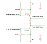
Please see the attachment. These limiters do not limit overall amplifier current. They only work to save the VAS transistors from burning-up in case someone accidentally turned the Input bias too high. The symmetrical VAS used in this kind of amplifiers is often feared for its bias being directly dependent on the input-stage bias. The limiters make sure that after a fixed maximum VAS bias current has been reached, any extra current coming from the input stages is prevented from entering the VAS transistors' bases and VAS current can't increase any more. For this the limiters need to be active during set-up.
Their downside is as previously mentioned, slowing down the amplifier too much. And for this they should be turned off after setup is done.
Attachments
...today I will try to play the V4 alongside the old and faithful V3 and will update about the sonics in the evening. 🙂
And after a whole day of listening to like 25-30 tracks all I have to say is that the V4 is my new reference.
It excels in each and every segment of the octaves. Compared to V3, mid-bass, mid-high and the highs are all equally good and in some cases noticeably better. I felt the mids a little softer than V3, some male-vocal tracks that used to occasionally feel a little out-of-place now sound alive and lovely! Female vocals come out with the usual PeeCeeBee signature i.e. absolutely fantastic! I think all previous peeceebees were more into girls. But V4 seemed to have balanced approach towards both male and female artists.
Finally the bass. Yes it is noticeably more deep, punchy and tight than V3 but is also very much synergistic with the rest of the audio band. What I liked most in the listening is its note-to-note stark contrast in the LF zone. The occasional disconnect between bass and mid that plagues some amplifiers is completely absent.
Again, my reference PeeCeeBee. 🙂
P.S.: Hey, all the above doesn't mean V3 is failing. It's still is the best among the simpler PeeCeeBees. Still very recommended!
the 47r in the base to emitter of the protection transistor will start to turn on when 8.5mA flows through this resistance and it will have reached full limiting when the current is trying to hit 12.8mA.
If that 8.5mA is too low to allow the circuit/VAS to operate correctly, then change the BE resistor to a lower value than 47r.
Let's suppose the VAS needs a degeneration value of 47r, then split that resistor.
28r between the base and emitter and the remainder of 18r or 20r on the emitter of the VAS.
You can choose any two resistor combination that adds up to the required degeneration value.
Hi Andrew.
Thanks for the suggestion. It is indeed a nice trick for the purpose.
I noticed that the VAS current can be increased to over 15mA with the protection transistors installed. I think the Philips BC5xxB transistors I am using have a higher vBE than the usually expected 600mV.
Even if we split the resistor, there might be situation that the combination of these resistors needs to be changed (either one of them or both). If both needs to be changed then double the mess, and if only one then its the same as changing the single 47R to like 39R for a higher ceiling. And as there is almost no free space on the board to add a pair extra resistors near the limiters it seems practical not to split the emitter resistors. (I really really don't want to make the board any bigger that it is now. (about 91mmx63mm))
Waiting for v4 with 2 pairs of mosfets... ha ha ha
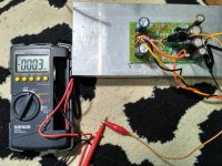
I have just finished building my second VSSA V2, supplied by 40 then 38Vac. But the heat sinks still cold not even a little bit warm after some tracks.. need your advice. Thank you
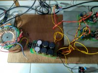
testing board, sorry for cable mess,
Best Regards
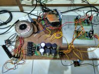
I have just finished building my second VSSA V2, supplied by 40 then 38Vac. But the heat sinks still cold not even a little bit warm after some tracks.. need your advice. Thank you
testing board, sorry for cable mess,
Best Regards
Attachments
Last edited:
...the heat sinks still cold not even a little bit warm after some tracks..
The MOSFETs are probably running at zero bias.
When the amp is on, what voltage do you read around the 1N4148 diode?
Can you upload a sharp close shot of the boards?
The MOSFETs are probably running at zero bias.
When the amp is on, what voltage do you read around the 1N4148 diode?
Can you upload a sharp close shot of the boards?
Ok i will measure the diode this afternoon. What is the voltage should read across that one?
- Home
- Amplifiers
- Solid State
- PeeCeeBee