Hello. 
Original V5 group buy thread >here<.
Feel free to post your questions/suggestions in this thread.

Edit: (July 25 2024)
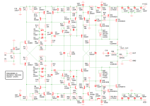
Schematic updated with latest component changes for best operation. Namely, R19, R20, C15, C16.
Original V5 group buy thread >here<.
Feel free to post your questions/suggestions in this thread.
Edit: (July 25 2024)
Schematic updated with latest component changes for best operation. Namely, R19, R20, C15, C16.
Attachments
Last edited:

Hi Gary.
It will run just fine with 35V rails, and we will gain a little more SOA for the power transistors. But RMS power into 8ohm will be limited to 75Watt or so. For 100W you can use 42V rails.
It will run just fine with 35V rails, and we will gain a little more SOA for the power transistors. But RMS power into 8ohm will be limited to 75Watt or so. For 100W you can use 42V rails.
Transistor matching?
There are a ‘few’ transistors on the V5, how critical is matching the different types?
There are a ‘few’ transistors on the V5, how critical is matching the different types?
Hi Vincent.
All the data I collected are with tests done with no matching between any of the transistors, neither small signal nor power.
Matching will always bring lower THD in a symmetrical amp. But a bit of disbalance might prevent the sonics from going into the clinical zone.
If the pairs do not deviate more than 50% in hFE then we're good.
That’s Music to my ears! Easy peazy parts gathering then. Hfe grade for 5551/5401’s?
Thanks Shaan 😉
Thanks Shaan 😉
Shaan,
I’m going to assume the pcb mounting holes for V5 and V4H are the same as such one can just pop the V5 board in place?
That would make my build really two amps in one! It will be nice to hear the differences between lateral mosfet output stage topology versus BJT. I think modern BJT’s have really come forward in their sonics. Looking forward to building this - but V4H first!
Best,
Anand.
Hi Oracle1.
35VAC will give around 50VDC. At that voltage you will get about 140W into 8ohm.
Thanks for the kind words.
35VAC will give around 50VDC. At that voltage you will get about 140W into 8ohm.
Thanks for the kind words.
Some would be willing to help out with disposing of those old lateral output V4H boards… 😎This was done so that members who want to upgrade, can do so easily.
Thanks for all the answers so far shaan, looks like there might be a lot of interest. Looking at several vendors, there could be supply issues with the On Semi output transistors through 2023 - have you looked at any other types for Q29 to Q32?
With +/- 35VDC rails ,output power at 75W will do me fine.
With +/- 35VDC rails ,output power at 75W will do me fine.
Yes....have you looked at any other types for Q29 to Q32?
TIP35C/36C
MJW21193/94
Both have been tested with the concept build and both perform very well.
Hi shaan,
Just looking into parts I have, can you answer the following thanks.
For C3,C4 and C15 (2200uF) - what is the voltage rating you are using to suit a can size of 10mm DIA and 5mm lead spacing?
For R49 and R50 at 0.22R / 5W - what part number are you using?
For R55 and R56 at 10R / 5W - what part number are you using?
Also looking at the schematic and board layout - there are some discrepancies with capacitor numbering - I assume you are finalizing this as you put a BOM together.
- Home
- Group Buys
- PeeCeeBee V5 discussion thread