Hello fellow members.
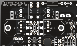
Here are the details of the V4H Revision 2 update. Below are the changes in order, followed by description of each.
1. A basic short circuit protection for output MOSFETs added.
There will be two diodes in each MOSFET between its gate and source (a 1N4148 and a 10V zener diode), limiting gate voltage to 10.7V and clamping drain current to safe limits in case of an output short with signal present at the input. These add about 4pF of capacitance to each gate which is negligible.
2. Q3/Q4 collector current limiting added.
R39/R40 added to Q3/Q4 collectors. These resistors will prevent overload of these two transistors in case an unsafe high voltage fast transient signal is presented at the input. As soon as a high current signal from the input pair tries to overload Q3/Q4 from their emitters to the rails via the base-emitter junction of Q9/Q10, these two resistors will kick in and protect Q3/Q4 from exceeding their safe-operation area.
3. Resistor and Capacitor hole diameter increased.
The pin holes for the 0.25W resistors and small capacitors have been widened in this update. Thicker pins will now go in without issue.
4. Mounting hole diameter increased.
The six mounting holes have been widened slightly so that M3 screws have a little area to move and allow for some tolerance in hole alignment. The outer diameter of the plated pad around these holes have been decreased slightly.
______________
Note: The short circuit protection diodes have been chosen to be SMD devices because without making significant changes to the layout it is impossible to accommodate eight more through hole components on this board. Don't worry though, these diodes will come pre-soldered on the boards at no extra cost. I initially thought of miniMELF for them, but while this glass package looks nice, it has zero compliance under mechanical stress. So the diodes will be SOD123 package. The packet with hundreds of these diodes is already on its way to me. 🙂
Thanks for your time and patience!
shaan
Attachments
Almost completed V4H project.
Both pcbs has been bench tested as per Shaan's manual.
Chassis is from a recycled faulty power amp.
Power supply is smps from Micro-Audio @+/-55Vdc rails.
https://ibb.co/FnjkHyf
Hi Meanie.
Very tidy layout! In case you haven't already, please install the mod posted in Post#1315.
 🙂
🙂Shaan, do you have the intention of making more GBs of this board in the future ? i have most of the components to build an another one but i can't decide at this moment.
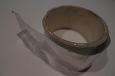
I've made revision two over one .Was quite impossible, caps beside the mosfets are nichicon muse, double size glued to the board with silicone, big silver mica tied to mosfets ,big resistor .... looking for aluminium to protect parts i finished in my tools room with a roll of adhesive aluminium tape used in air conditioning conducts ,easy and cheap to buy . Much thicker than kitchen one it's a genuine marvel to cut and work , the left over is minimal and easy to remove.
I've made revision two over one .Was quite impossible, caps beside the mosfets are nichicon muse, double size glued to the board with silicone, big silver mica tied to mosfets ,big resistor .... looking for aluminium to protect parts i finished in my tools room with a roll of adhesive aluminium tape used in air conditioning conducts ,easy and cheap to buy . Much thicker than kitchen one it's a genuine marvel to cut and work , the left over is minimal and easy to remove.
Shaan, do you have the intention of making more GBs of this board in the future ? i have most of the components to build an another one but i can't decide at this moment.
Yes of course, if more people keep showing interest then why not.
I've made revision two over one .Was quite impossible, caps beside the mosfets are nichicon muse, double size glued to the board with silicone, big silver mica tied to mosfets ,big resistor .... looking for aluminium to protect parts i finished in my tools room with a roll of adhesive aluminium tape used in air conditioning conducts ,easy and cheap to buy . Much thicker than kitchen one it's a genuine marvel to cut and work , the left over is minimal and easy to remove.
I don't fully understand what you meant. Was the Rev1 mod hard to install? I agree it is a little tight between the electrolytics but with careful and slow approach it can be done safely.
Hi Jorgovanko.
4K7 is the value that I am looking at after some experiments. Will post final value in updated schematic early next week.
4K7 is the value that I am looking at after some experiments. Will post final value in updated schematic early next week.
when will pcb V4H Revision 2 update be available
Hi Deps.
Boards will be ready by August 25. Entry for this GB will be closed tomorrow.
Hi Meanie.
Very tidy layout! In case you haven't already, please install the mod posted in Post#1315.
Ok, will do those diodes mods, also an excuse to give the rusty chassis a fresh coat of paint.
Thanks
UPDATE:
Torvbakkane - 6 PCBs - PAID
Faizal Mansar Alam - 2 MODULES - PAID
J.M.K - 4 PCBs - PAID
prairieboy - 2 PCBs - PAID
Pistollero - 2 PCBs + MOSFETS - PAID
RobSoet - 4 PCBs + MOSFETS - PAID
Rick G - 4 PCBs - PAID
blek stena - 2 PCBs - PAID
nrabbit - 2 PCBs + MOSFETs - PAID
Greg1017 - 2 PCBs + MOSFETS - INVOICE SENT
satmmc86 - 2 MODULES - PM SENT
Deps -2 PCBs
Boards will be ordered tomorrow August 1. Expected time of getting the batch at hand August 25. I will print a few extras so that people in the queue still get a chance to get their pair (if someone else doesn't already take them before).
Thanks everyone for your interest in peeceebee.
Rev2 update details in next post.
Are there any thermal concerns if boards are mounted upside-down? The signal in up - output resistors down.
GB UPDATE:
Torvbakkane - 6 PCBs - PAID
Faizal Mansar Alam - 2 MODULES - PAID
J.M.K - 4 PCBs - PAID
prairieboy - 2 PCBs - PAID
Pistollero - 2 PCBs + MOSFETS - PAID
RobSoet - 4 PCBs + MOSFETS - PAID
Rick G - 4 PCBs - PAID
blek stena - 2 PCBs - PAID
nrabbit - 2 PCBs + MOSFETs - PAID
deps - 2 PCBs - PAID
Greg1017 - 2 PCBs + MOSFETS - INVOICE SENT
satmmc86 - 2 MODULES - PM SENT
Note:
Post#1 has been updated with Revision 2 info. New schematic, layout snapshot, setup guide and BOM have also been shared in Post#1.
🙂
- Home
- Group Buys
- PeeCeeBee V4H GB