Hi.
What value does it show in output offset without any trimming?
Output offset shows approx. 300mV
JM
Output offset shows approx. 300mV
JM
Ok. Turn VR1 anticlockwise and VR2 clockwise and check if offset reaches zero.
Ok. Turn VR1 anticlockwise and VR2 clockwise and check if offset reaches zero.
I did contrary, as it was negative.
Little adjustment, and I'm very close to zero !
Thanks a lot.
I'll go out for a walk, and then proceed to mosfet biasing.
Should not be a problem.
JM
I did contrary, as it was negative.
Little adjustment, and I'm very close to zero !
Thanks a lot.
I'll go out for a walk, and then proceed to mosfet biasing.
Should not be a problem.
JM
Good to know.
 🙂
🙂Good to know.
Mosfet bias brought back to 215mV
But it's heatsink is really hot after 15mn !!
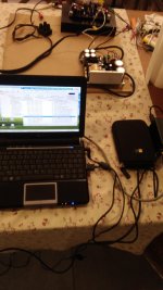
My workbench's mess attached, no shame !
JM
Attachments

Mosfet bias brought back to 215mV
But it's heatsink is really hot after 15mn !!
My workbench's mess attached, no shame !
JM
Thanks for the pic. With heatsinks lying flat it should get hotter than usual as airflow is restricted. All looks normal.
Thanks for the pic. With heatsinks lying flat it should get hotter than usual as airflow is restricted. All looks normal.
I'm going to have 1 fan on top of each of my smps in my enclosure,
as I'm living in a hot place, and as this amplifier is located in a not so well ventilated shelf. Otherwise it's going to get much too hot in my enclosure,
not so good for electronics.
What is the minimum bias I should have to keep it stable ?
Is 150 mV still OK ?
JM
It can be stabilised at any bias. But that bias has a direct relationship with cooling required. So one has to find it out in a given cooling situation.
If it is acceptably warm then 150mA is just fine. If it still gets too hot, then try 100mA.
It can be stabilised at any bias. But that bias has a direct relationship with cooling required. So one has to find it out in a given cooling situation.
If it is acceptably warm then 150mA is just fine. If it still gets too hot, then try 100mA.
OK, I'll take care of this later when my enclosure will be ready.
Next step for me is to fix my other (damaged) pcb, will take time as I'll have to order some parts .......
JM
Listening music with the newborn baby now for 1h1/2 on my 3 way floorstanding speaker.
Excellent sound, couldn't say more, even though it's in mono (downmixed in foobar). Lot of headroom power.
JM
Happy to know you like the output.

Happy to know you like the output.
........ and now well motivated to fix my damaged board in order to have my stereo power amp working !!
3 Exicon mosfets damaged. 😕Completely my fault.
One of my digital multimeter had a feeble battery (didn't notice),
wrong mV readings and you know what happened !!
JM
........ and now well motivated to fix my damaged board in order to have my stereo power amp working !!
🙂3 Exicon mosfets damaged....

MORE SMOKE !!
R26 fried, as I was into starting some measurements with my scope and low freq generator.

I had a 8ohm power resistor - exploded 😕- (on heatsink) as load on the output.
I guess I had a bit too much voltage on the input.
LEDs still lighting up. Looks like the BJTs are OK and no other obvious damage.
Should I check anything else in particular before starting again for more fun ?
Thanks again ......
JM
R26 fried, as I was into starting some measurements with my scope and low freq generator.
I had a 8ohm power resistor - exploded 😕- (on heatsink) as load on the output.
I guess I had a bit too much voltage on the input.
LEDs still lighting up. Looks like the BJTs are OK and no other obvious damage.
Should I check anything else in particular before starting again for more fun ?
Thanks again ......
JM
Last edited:
MORE SMOKE !!
R26 fried, as I was into starting some measurements with my scope and low freq generator.
I had a 8ohm power resistor - exploded 😕- (on heatsink) as load on the output.
I guess I had a bit too much voltage on the input.
LEDs still lighting up. Looks like the BJTs are OK and no other obvious damage.
Should I check anything else in particular before starting again for more fun ?
Thanks again ......
JM
Check Q3, Q4, Q9, Q10.
I hope this kind of fun doesn't happen to you again.
Check Q3, Q4, Q9, Q10.
I hope this kind of fun doesn't happen to you again.
Diagnosis: Q4 fried too.
So, I'm going to replace R26 + Q4, and R25 + Q3 to avoid belated failure as they my have suffered too on the other side.
Thanks a lot for you help, I told you I'm a pain ......... 🙂
JM
Don't worry about the temperature. My heatsinks have about 48° C after 2 hours, while Exicons direct contacted have 78° C.
Temperature feeling is hotter then it is in real. F.e.g. You do a bathing at home and water does have 38° some will think/feel it's too hot to go in.
Good Luck
Jo
Temperature feeling is hotter then it is in real. F.e.g. You do a bathing at home and water does have 38° some will think/feel it's too hot to go in.
Good Luck
Jo
Diagnosis: Q4 fried too.
So, I'm going to replace R26 + Q4, and R25 + Q3 to avoid belated failure as they my have suffered too on the other side.
Good idea.
Thanks a lot for you help, I told you I'm a pain ......... 🙂
JM
No problemo, I'm happy to help. 🙂
Good idea.
No problemo, I'm happy to help. 🙂
It looks like I accidentally had about 10V on my generator's output ........ 😡
no wonder what happened.
JM

- Home
- Group Buys
- PeeCeeBee V4H GB