As far as I know shipping from Austria to Greece is ok at the moment. I might be a forwarding point for this shipment.
Lohk, many thanks for your offer, but I 'll have to pay also the transportation fees from Austria to Greece.
So I prefer to wait for the direct shipping.
So I prefer to wait for the direct shipping.
Member
Joined 2021

Dear Shaan and Fellows,
As this circuit is originally design as an headphone amp, shall I change the value of R55, R56, R57, R58 to increase the magnification ratio for pre-amp? If so, what is the best value for?
Thanks,
Daniel
As this circuit is originally design as an headphone amp, shall I change the value of R55, R56, R57, R58 to increase the magnification ratio for pre-amp? If so, what is the best value for?
Thanks,
Daniel
Hi Daniel.
It was originally designed as a preamp. Later I changed the output transistors from TO92 package to TO126 for allowing more bias current necessary for headphone application. I initially thought of paralleling like a dozen small BJTs but I looked at the prototype and thought "Ohh man for a simple pre this is a forest already, let's not play around too much." 😀
Anyways, you can freely increase the four resistors to almost whatever value you want and get your desired amplification. I have tested with 10Kohm that gave about 22dB of gain without any ill effect other than bringing HF -3dB cutoff down to 500KHz, from the default 5MHz, and an slight increase in output impedance. Keep in mind that increasing these resistors will also increase output bias, so I suggest you first decrease bias to less than a milliamp, change the resistors, then re-calibrate bias and offset.
Bests.
p.s. Decreasing these resistors below 470ohm is not recommended due to chance of oscillation.
Hi Daniel.
It was originally designed as a preamp. Later I changed the output transistors from TO92 package to TO126 for allowing more bias current necessary for headphone application. I initially thought of paralleling like a dozen small BJTs but I looked at the prototype and thought "Ohh man for a simple pre this is a forest already, let's not play around too much." 😀
Anyways, you can freely increase the four resistors to almost whatever value you want and get your desired amplification. I have tested with 10Kohm that gave about 22dB of gain without any ill effect other than bringing HF -3dB cutoff down to 500KHz, from the default 5MHz, and an slight increase in output impedance. Keep in mind that increasing these resistors will also increase output bias, so I suggest you first decrease bias to less than a milliamp, change the resistors, then re-calibrate bias and offset.
Bests.
p.s. Decreasing these resistors below 470ohm is not recommended due to chance of oscillation.
Thanks Shaan! Got it. 🙂
Hi Shaan, just received my board today, one question I do not have any of BC transistors in my stock, I have some KSA992 and Ksc1845 both are the FTA termination, hfe between 300 to 600, these should be ok to use yes?, I am asking because I dont want surprises 🙂), if not I will just order the type in the BOM, I have soldered allready the BD139 and 140 allready.
Thanks,
Florin
Thanks,
Florin
Hi Outtek.
The BCs with their medium hFE of 250-350 will work best in this preamp. So I will suggest you get them.
The BCs with their medium hFE of 250-350 will work best in this preamp. So I will suggest you get them.
Hi Shaan, one more question, why the need for so many 1000uF caps? It does need low current the whole circuit, could one use also many 470uF caps and should achieve bassically the same result, no? I have ordered the 1000uF allready but the one I could find are low esr type and so many in parallel would make the diodes suffer alot each start no?
Thanks,
Florin
Thanks,
Florin
Hi Florin.
You are right the diodes seem to suffer a bit but I have tested it extensively for 6 months since March 2020 and still playing everyday, and have found no degradation in their performance and neither any significant heating during inrush. So you may rest assured it won't hurt them, but feel free to use off board bridge module in case you do not want to stress the diodes. BTW, the 4007 can take 30A of worst case inrush but I wonder if a 30VA transformer can give that. Meaning, the transformer's secondary's resistance itself will limit the inrush to a safe value for the diodes. The scene will change with a 300VA transformer though, the diodes will face a much stronger surge of charging current, but I guess very few people will use such a transformer with 15V/20A secondaries to power this preamp. 🙂
I agree that so many 1000uF may not be needed and you can make it work using 470uF, but after looking at the prototype with the freshly soldered banks I thought it just looked cool. That aside, a higher capacitance means higher ripple attenuation before regulation, which is always a good thing, the rails are very quiet indeed. But while one could use just a pair of 10000uF and call it a day, the impedance of 10x1000uF will be lower than 1x10000uF, meaning better ripple rejection. Plus I liked that the rail trace of the banks is quite long due to the arrangement, possibly adding some inductance to the rails which may help with removing some high frequency noise from the rails.
Hi Shaan, me again, in the schematic the two VR are marked as 1K but the BOM says that all the VR are 5K multiturn, the BOam is correct or the schematic? So far I have populated most of the board with values from the BOM. Hopefully I didnt miss any post about a different value. I didnt had all the 100nF/100V at working voltage of 100V but at 63V, should be ok looking at the schematic.
Thanks,
Florin
Thanks,
Florin
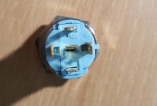
How to connect 12v led?
Now casing all the parts...but I have a question.
The led switch has 5 pins and requires 12v.
I think there are three ways as follows.
1. 220 mains
2. 2nd of the troidal (18v)
3. the psu of PeeCeeBee (15v)
Which is the most recommended and How?
Thanks.
Now casing all the parts...but I have a question.
The led switch has 5 pins and requires 12v.
I think there are three ways as follows.
1. 220 mains
2. 2nd of the troidal (18v)
3. the psu of PeeCeeBee (15v)
Which is the most recommended and How?
Thanks.
Attachments
Last edited:
Hi Ksjung88
TP1 and TP2, with a 10K-22K resistor in series (LED may remain lit for quite some time until the cap bank drains). Or the two AC input of the board, with a single diode rectifier and 10k-22k resistor in series and a 100uF capacitor to smooth it slightly (LED will shut down quickly at power off).
TP1 and TP2, with a 10K-22K resistor in series (LED may remain lit for quite some time until the cap bank drains). Or the two AC input of the board, with a single diode rectifier and 10k-22k resistor in series and a 100uF capacitor to smooth it slightly (LED will shut down quickly at power off).
- Home
- Group Buys
- PeeCeeBee Preamplifier GB