
Pot for SIG
Mouser Part. No. 858-P092N-QC20BR20K
TT-Electronics (100000 cycles)
Mouser Part. No. 688-RK0971210Z2M
Alps (15000 cycles)
Can anyone know where can buy this 20K Or 50K Dual LIN Potentiometer for "SIG" ?
Any brand and model suggest ?
Mouser Part. No. 858-P092N-QC20BR20K
TT-Electronics (100000 cycles)
Mouser Part. No. 688-RK0971210Z2M
Alps (15000 cycles)
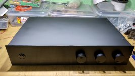
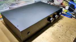
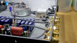
Just finished. 🙂🙂🙂
Attachments

Impeccable PeeCeeBee Preamp (aka Black Beauty) Shaan!! Beautifully done.
Can you post information/link for the rotary selector switch and pcb, and the push-button power switch. Thank you.
Can you post information/link for the rotary selector switch and pcb, and the push-button power switch. Thank you.
Hi Vincent.
Thanks. Here are the links.
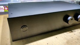
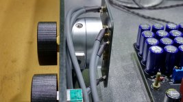
LED Ring type Switch -Blue_latching_BLACK
EIZZ Rotary Audio Input Selector Switch 3003800 with PCB

Thanks. Here are the links.
LED Ring type Switch -Blue_latching_BLACK
EIZZ Rotary Audio Input Selector Switch 3003800 with PCB
Nice work shaan,
Could you please post the dimensions of the enclosure (W x H x D). I like the amount of working space.
Could you please post the dimensions of the enclosure (W x H x D). I like the amount of working space.
“LED Ring type Switch -Blue_latching_BLACK“ Anti-vandal type push button switch, very good price , around 6$/ each . I am curious if one switch like that is suitable for one stereo amp v4h .
Nice work shaan,
Could you please post the dimensions of the enclosure (W x H x D). I like the amount of working space.
Thanks. The dimensions are 15"x9.5"x3".
“LED Ring type Switch -Blue_latching_BLACK“ Anti-vandal type push button switch, very good price , around 6$/ each . I am curious if one switch like that is suitable for one stereo amp v4h .
Yes it is sufficient.
Hello Shaan , any news about shipping to Portugal?
Tks
Hi Pistollero.
I will check with PO tomorrow and update you.
Thanks.
Shaan, where did you get the enclosure?
Handbuilt at home. 🙂
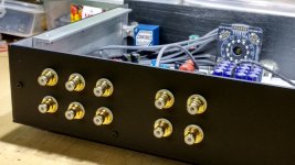
Just finished. 🙂🙂🙂
Very nice Shaan 🙂
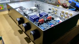
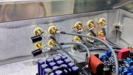
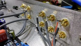
One quick question on the outputs you have connected a cap + resistor with the signal side and the grounds, any specific reason why that is needed? And also where this outputs connected to as the cables go beneath the PCB and not visible from the pics. Is this 2 different outputs and what are the differences?
Thanks
Hi Manniraj.
Thanks.
The electrolytics are connected from before C27/C28 and act as a second hot output with higher current capacity in order to drive headphones if necessary, or just act an auxiliary output for connecting a subwoofer amp. As the 22ohm was bypassed for the electrolytic I installed a 33ohm(didn't have 22ohm ready at hand) in series and installed a 15kohm from its negative pin to ground to give the electro a charging path. The offset is set slightly positive to bias the electros in the correct polarity.
Just finished. 🙂🙂🙂
So can it now drive both the power amp and sub at the sametime without any issue with the current drive capability of the preamp? Also what value is the cap?
Thanks
Hi Shaan,
If shipping to Portugal is still not an option for you, I can ship Pistollero my PeeCeeBee preamp board, just ship me his. I still have a few projects to complete before I start your preamp.
If shipping to Portugal is still not an option for you, I can ship Pistollero my PeeCeeBee preamp board, just ship me his. I still have a few projects to complete before I start your preamp.
- Home
- Group Buys
- PeeCeeBee Preamplifier GB