Hi Shaan,
Thanks for your design and PCB . It is very elegant sound /warmly as good as my tube preamp, much low background noise and operation stable. I listened few days (around 10 hours) and feel all the words from singer voice clear and concrete than my before equipment.
Indeed, it is much wroth to all my given time and coins. :>
Just one thing i want to clarify, how much voltage gain of this preamp ? My system is DAC -> Passive preamp (resistive load) -> Pee Preamp -> PowerAMP , I find the gain more less than my previous preamp.
My Pee Preamp is bypassed C1, not sure it will make the gain less ?
How can i change the component to get more voltage gain ?
CK
Attachments
Last edited:
Hi Shaan,
Thanks for your design and PCB . It is very elegant sound /warmly as good as my tube preamp, much low background noise and operation stable. I listened few days (around 10 hours) and feel all the words from singer voice clear and concrete than my before equipment. Indeed, it is much wroth to all my given time and coins. :>
Hi CK.
Glad to hear you like the preamp's sound.

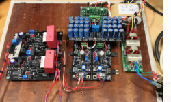
You seem to have cut the PCB and put a secondary regulator module in between. Interesting.
Did you take the PCB from one of the two members who joined from HongKong? I don't see your entry in the GB.

Just one thing i want to clarify, how much voltage gain of this preamp ? My system is DAC -> Passive preamp (resistive load) -> Pee Preamp -> PowerAMP , I find the gain more less than my previous preamp. My Pee Preamp is bypassed C1, not sure it will make the gain less ? How can i change the component to get more voltage gain ?
CK
Very easy. Increase R55,56,57,58 to 2k2 for about 5 times gain. If more is needed then increase to 2k7. Re-trim output bias and offset after replacing the resistors. Done.
If your source doesn't have DC at its output then you can bypass C1. Still it's good to have a capacitor there.

Hi Shaan,
Yes, i cut it and use your capacitor bank with my standalone parallel regulator. During i do this modification moment, i find the schematic D11 & 12 label swapped, which compare to PCB silk print. Actually, it is not a big deal who those follow the PCB w/o modifying. However, my change need two jumpers short 2 diodes in rectification will have problem. It was because i use active bridge to replace the diodes.
This time my fried help me order, he is Daniel.
Current design is R55~58 is 1K , so what is the existing voltage gain ? how to do the calculation ? I want to take existing gain as reference then to make my optimal gain value.
Sure , to play safe it should via C1, but for better sound result, i skip it now 😛
Last edited:
Hello Shaan , any news about shipping to Portugal?
Tks
Hi Shaan,
If shipping to Portugal is still not an option for you, I can ship Pistollero my PeeCeeBee preamp board, just ship me his. I still have a few projects to complete before I start your preamp.
Hi Nuno. Hi Vincent.
Still no option for Portugal from here. I will ship the preamp board to Vincent.
Group buy from Poland:
audiostereo - 14 PCB
Hi Shaan, do add me to the preamp GB for 1 assembled unit.
If you still have GB open, I am in for one!
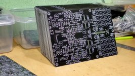
A packet of 50 preamp boards reaching me by 15th.

Hi Shaan,
Yes, i cut it and use your capacitor bank with my standalone parallel regulator. During i do this modification moment, i find the schematic D11 & 12 label swapped, which compare to PCB silk print. Actually, it is not a big deal who those follow the PCB w/o modifying. However, my change need two jumpers short 2 diodes in rectification will have problem. It was because i use active bridge to replace the diodes.
This time my fried help me order, he is Daniel.
Current design is R55~58 is 1K , so what is the existing voltage gain ? how to do the calculation ? I want to take existing gain as reference then to make my optimal gain value.
Sure , to play safe it should via C1, but for better sound result, i skip it now 😛
Gain is roughly the value of these resistors divided by 470. I would recommend you keep C1 on board.
Hi Theodosis.
No update yet on the website. I will check with the PO again tomorrow and update you subsequently.
No update yet on the website. I will check with the PO again tomorrow and update you subsequently.
Hello Shaan , do you have any news about shipping to Greece ?
Thanks a lot.
Hi Theodosis. Still no shipping option for Greece. 🙁
- Home
- Group Buys
- PeeCeeBee Preamplifier GB