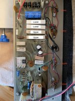
Measured the below voltages (all voltages +DC, referenced to chassis ground), see attached picture.
A. .002
B. .002
C. .143
D. .144
E. .103
F. .102
G. .220
H. .219
This means I have ~147 ma through my lower emitter resistors and ~113 ma through my upper emitter resistors.
Disconnecting bases of lower transistors gave me ~59.8 VDC across the 3500uf cap can, ~26.2 VDC at the upper transistor emitters, and ~26.1 VDC at the positive of the 1000uf speaker cap.
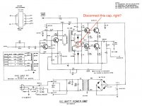
I'll try disconnecting the .02 uf cap that connects to the bases of the lower output transistors next.
A. .002
B. .002
C. .143
D. .144
E. .103
F. .102
G. .220
H. .219
This means I have ~147 ma through my lower emitter resistors and ~113 ma through my upper emitter resistors.
Disconnecting bases of lower transistors gave me ~59.8 VDC across the 3500uf cap can, ~26.2 VDC at the upper transistor emitters, and ~26.1 VDC at the positive of the 1000uf speaker cap.
I'll try disconnecting the .02 uf cap that connects to the bases of the lower output transistors next.
Attachments
No, the result of the disconnecting the bases of the lower transistors proves they are leaking. Iceo is 147 ma each in your test, much too high. Current limited only by the bias network of the upper transistors. Iceo is measured with bases disconnected.
New transistor time. Where are you? I've had bad luck with quality of parts from local parts stores, except NTE 60 output transistors were okay (but expensive).
If you want to save $9 freight, put a .70 cent .022 uf 100 v disc cap in the box, but your probably don't need it. those don't fail often. Get some fuses or solder or something in the box. Real distributors charge a handling fee for orders below a certain amount. If the handling fee kicks in below $40, put some MJE15028 and MJE15029 in there, plus some MPSA56 and MPSA06 and 4 four TO220 heatsinks. Plus a 2 k trim pot. You'd need those to build a TGM8 or AX6 board replacement for the interstage transformer. Look at those threads for a compete schematic : Retro Amp 50W Single Supply - Page 22 - diyAudio
With heatsinks on the driver transitors & VAS transistor these boards will drive 2 parallel output transistor for 100 or 200 W.
Last edited:
I'm on the west coast of the USA and bought these transistors from Digikey a few weeks ago. It seems unlikely that these brand-new parts are bad, perhaps I should order new sockets as well? Would these work?
And to be clear, the 147ma I measured was before I disconnected the bases of the lower transistors.
You need to measure the voltage drop across the lower emitter resistors with the lower output transistor bases disconnected. Then divide by .68 ohms to get current. Current I lower transistors >= to that out upper transistors emitters, the lower transistors are leaking at 37 v even though they didn't leak at 12 v by your test.
MJ15024 are excellent, if a bit over tough for a 2n3055. Keystone makes great sockets, but a bases disconnected Iceo test on lower two transistors @ 37 v will prove sockets okay, if all the current going in the collectors of the lower output transistors, is coming out the emitters.
MJ15024 are excellent, if a bit over tough for a 2n3055. Keystone makes great sockets, but a bases disconnected Iceo test on lower two transistors @ 37 v will prove sockets okay, if all the current going in the collectors of the lower output transistors, is coming out the emitters.
Should I disconnect the .02 uf cap for this voltage test (with lower transistor bases disconnected)?
No. That test was for if the lower output transistor tested good. Not leaking with the bases disconnected.
Tested emitter resistor voltages: all 4 resistors showed ~0VDC drop when lower transistor bases were disconnected (regardless of .02 cap being lifted or connected).
Should I go ahead and replace the lower transistors and transistor sockets?
Should I go ahead and replace the lower transistors and transistor sockets?
Yes. The sockets haven't been demonstrated as bad, but 45 year old doped cardboard is not exactly a forever material.
Well, it looks like your picture. But I've never owned one of these. My first transistor amp (1970) had wires soldered to the transistor legs. Use your eyes.
Do you have these? I wouldn't wait on them to try out your MJ15024's. Just the plastic coated paper used in the early 70's (the brown stuff) was not designed for 50 years life. The mica washer too has a possibility of shorting after 30 years. If you use a mica washer, you'll need some heat sink compound not filled with silver metal, as the Dow corning 340. I've been using GC brand heat sink compound for 46 years, and have some workman compound of about the same age.
Do you have these? I wouldn't wait on them to try out your MJ15024's. Just the plastic coated paper used in the early 70's (the brown stuff) was not designed for 50 years life. The mica washer too has a possibility of shorting after 30 years. If you use a mica washer, you'll need some heat sink compound not filled with silver metal, as the Dow corning 340. I've been using GC brand heat sink compound for 46 years, and have some workman compound of about the same age.
Last edited:
I used new mica washers and heat sink compound when I installed the new transistors a few weeks ago.
I don't have these sockets on hand, should I try with alligator clips first (and no sockets) to see if that fixes the issue?
I don't have these sockets on hand, should I try with alligator clips first (and no sockets) to see if that fixes the issue?
No, don't install the new transistors without having the heat conducted to the heat sink by the mica washers and heat sink compound.
These are new MJ15024 you are experimenting with?
Hang on, you said all emitter current went to zero, both upper & lower emitter resistors, when you disconnected the bases of the lower transistors. You said lower transistor collector voltage went near the main supply voltage, the "can cap" voltage.
I correct what I said. No lower transistor emitter current with no base drive current means the lower output transistors are good, and too much base current is driving the collectors too close to ground.
Since you pulled the .02 uf cap, the excessive idle base current is getting to the lower transistor bases from some other way. Try putting the .02 uf cap back, and disconnecting the interstage transformer from the lower transistor bases. Maybe the excessive idle base current is coming from there. then measure the speaker cap upper voltage and the idle current through the upper & lower emitter resistors.
Last edited:
Yes, these are all new output transistors.
Hmm, how do I remove the interstage transformer from the lower bases? Fully remove it from the board and reconnect the green, orange, and blue windings with alligator clips?
Hmm, how do I remove the interstage transformer from the lower bases? Fully remove it from the board and reconnect the green, orange, and blue windings with alligator clips?
Disconnected the "yellow" winding (as marked on the SCH), reconnected .02 cap and lower transistor bases, and rechecked voltages. All voltages DC measured wrt chassis ground. See picture in post #81 for labels. Speaker cap upper voltage was ~+26.4 VDC.
A. -.009
B. -.009
C. 26.50
D. 26.50
E. -.009
F. -.009
G. 26.50
H. 26.50
Looks like very little current draw across emitter resistors (DBT was dim in this test as well); does this mean the interstage transformer is bad? If so, am I SOL until another broken PA-200 (or similar model) floats by on eBay? Looks like it is a "DC-298" or 70500298 per SCH and text on the transformer itself.
Last edited:
Yes. Sorry about my mistake in post 82. I think a guitar head from that era may have interstage transformer too, but I don't play guitar so I've never had one apart. Advantage of old peavey mastodons, you can get the schematic diagram from the model number without buying the product. The look for an interstage transformer before you put in a bid on ebay or craigslist or gumtree.
Since PA200 has a npn input transistor, the interstage transformer can be replaced by some parts of a tgm8. https://www.diyaudio.com/forums/sol...ased-rod-elliot-p3a.html?highlight=tgm8+bigun
You can reuse the power transformer, rectifiers, can cap, speaker cap, output transistors case, jacks, heat sinks, volume pot, all that niddlety stuff. TGM8 board less output transistor part should fit in same space as interstage transformer. Reason for the transformer, in 1972 transformers were $4 and the 3 TO5 transistors, the VAS & the 2 drivers, were $5 each, the round heatsinks about $1.50. Now incredibly superior MJE15028/29 transistors are about $1.20, the flat TO220 heat sinks are about $.80.
If you download the tgm8 schematic, he favors wimpy drivers & VAS like BD139/140, which is fine for one pair 2sa1943/2sc5200 output transistors @50w but you have two pairs npn & 200 W. I see no reason not to use MJE15028/29 with heat sinks for a lot more drive current to the output transistors, to drive the pair of them. One liability of tgm8, he uses pnp upper output transistors, which in your case would be MJ15025. More $$.
Cheaper is AX6 which uses npn output transistors exclusively, but you would need a pnp input transistor like MPSA56. Fits on a 4"x4" board and that is with output transistors on the board, which you don't need. I have my output transistors physically located away from the driver board, 6" by wire and 3" by physical distance, and my unit doesn't oscillate. Downside to AX6, you can't buy the PCB. Prasi in India made some but I never found a way to pay him; he won't use e-bay so he doesn't drown in government paperwork. My computer is not new enough for pay-pal India's requirements for payment that way.
PCB's you can buy from ebay/alibaba are 99.999% split supply amps, which is not the kind of power transformer you have.
Happy shopping & diy modification.
Thanks indianajo. Unfortunately, the TGM8 files way above my rudimentary electronics background. Looks like I'll have to wait for another broken Peavey to float by...
I appreciate all the help!
I appreciate all the help!
For curiosity's sake, I removed the interstage transformer from the board and took resistance readings: see below (all values in ohms). It seems like the blue wire might be disconnected; would this cause the excessive idle base current I was seeing before?
Red - Black: 83.9
Red - Orange: 47.1
Red - Yellow: 47.1
Red - Green: 43.9
Red - Blue: open
Black - Orange: 43.8
Black - Yellow: 43.8
Black - Green: 40.7
Black - Blue: open
Orange - Yellow: 3.7
Orange - Green: 3.6
Orange - Blue: open
Yellow - Green: 3.6
Yellow - Blue: open
Green - Blue: open
DVM Leads: .1 ohms
Attachments
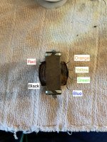
The Blue wire might be open circuit, but there should be no continuity between the separate windings. According to the schematic in post #81, Black/Red winding, Orange/Green winding, Yellow/Blue winding should be insulated from each other. I think I might have a PA-200 for parts. I will check if it is similar model when I get to my basement later.
- Home
- Amplifiers
- Solid State
- Peavey PA-200 Powerup With Dim Bulb Tester and Variac