Check the base-to-emitter voltages of the output transistors, and the voltages across the emitter resistors.
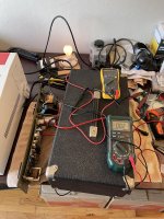
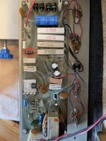
Finally found some time to check voltages: see attached picture (second picture). Are these values expected?
I also noticed when checking voltages that I have significant resistance between the left side of the emitter resistors (when looking at my picture) and chassis ground (measurements are all over the place). Could I have a bad ground connection on the PCB? The PCB mounting screws have good continuity to the chassis...
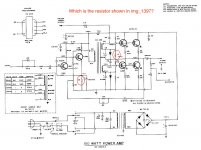
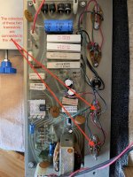
Digging deeper, I managed to confuse myself with the schematic. Which resistor on the SCH corresponds to the resistor highlighted in the first picture? I would have expected it to be the 22 ohm on the SCH, but the emitter resistor legs attached to this 22 ohm resistor are continuous to the collector of a pair of the output transistors, which leads me to believe the 22 ohm on the board is the 15 ohm highlighted on the SCH.
I also noticed when checking voltages that I have significant resistance between the left side of the emitter resistors (when looking at my picture) and chassis ground (measurements are all over the place). Could I have a bad ground connection on the PCB? The PCB mounting screws have good continuity to the chassis...
Digging deeper, I managed to confuse myself with the schematic. Which resistor on the SCH corresponds to the resistor highlighted in the first picture? I would have expected it to be the 22 ohm on the SCH, but the emitter resistor legs attached to this 22 ohm resistor are continuous to the collector of a pair of the output transistors, which leads me to believe the 22 ohm on the board is the 15 ohm highlighted on the SCH.
Attachments
Sorry, been busy doing something for the wife.
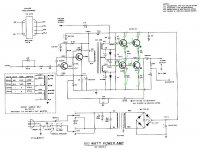
The right end of the 1000 uf capacitor pretty obviously connects with the red wire to the collector of the top transistor. Both points should be ~1/2 the power supply or 37 v. If the collector of the transistor is 37 and the right end of the 1000 uf capacitor is 0, there is a bad solder joint. If the collector of the output transistor is @ 0 volts or 1 volt or something, the output transistor is shorted, or the installation is incorrect to short it to almost ground.
The 22 ohm resistor is supposed to go to the emitter of the TO220 transistor on the little heat sink. I don't see any way it could be continuous to the collector of the two bottom output transistors, which should be 74 volts or so. Even if the TO220 driver transistor was shorted the 22 ohm resistor should be 1500 ohms away from +74. If both the output transistor were shorted C-E and the interstage transformer were shorted, the 22 ohm resistor still should be 1500 ohms away from +74. one end of the 22 ohm resistor does go to speaker ground. If you measure 22 ohm resistor top to +74 your ohmmeter will have to charge up the rail capacitor which means the reading should climb til it reaches the leakage resistance of the rail capacitor.
More to the point, the voltage across the .68 ohm emitter resistors should indicate how much idle current is running through the output transistors. Should be 20 - 40 ma, dividing V by R .68 ohms.
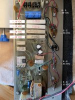
Your .08 v readings on ground side of emitter resistors may indicate you need a stainless star washer on the ground connection. I don't see what is between your board ground and the speaker ground. But 2 of those emitter resistors should be reading at 37 volts to speaker ground with the power on. Or 1/2 the rail voltage as limited by the light bulb in series with the AC plug.
The right end of the 1000 uf capacitor pretty obviously connects with the red wire to the collector of the top transistor. Both points should be ~1/2 the power supply or 37 v. If the collector of the transistor is 37 and the right end of the 1000 uf capacitor is 0, there is a bad solder joint. If the collector of the output transistor is @ 0 volts or 1 volt or something, the output transistor is shorted, or the installation is incorrect to short it to almost ground.
The 22 ohm resistor is supposed to go to the emitter of the TO220 transistor on the little heat sink. I don't see any way it could be continuous to the collector of the two bottom output transistors, which should be 74 volts or so. Even if the TO220 driver transistor was shorted the 22 ohm resistor should be 1500 ohms away from +74. If both the output transistor were shorted C-E and the interstage transformer were shorted, the 22 ohm resistor still should be 1500 ohms away from +74. one end of the 22 ohm resistor does go to speaker ground. If you measure 22 ohm resistor top to +74 your ohmmeter will have to charge up the rail capacitor which means the reading should climb til it reaches the leakage resistance of the rail capacitor.
More to the point, the voltage across the .68 ohm emitter resistors should indicate how much idle current is running through the output transistors. Should be 20 - 40 ma, dividing V by R .68 ohms.
Your .08 v readings on ground side of emitter resistors may indicate you need a stainless star washer on the ground connection. I don't see what is between your board ground and the speaker ground. But 2 of those emitter resistors should be reading at 37 volts to speaker ground with the power on. Or 1/2 the rail voltage as limited by the light bulb in series with the AC plug.
Last edited:
It looks overbiased, based on those voltages. That shouldn’t be happening with new diodes and 15 ohm resistors (unless the diodes are in backwards, but the orientation on the board makes sense to me). What happens if you temporarily jumper over those two diodes (use two clip leads). This should drop the voltage across the emitter resistors to zero, and force the output voltage to “center”. If it doesn’t, there is something else wrong that needs fixing. I don’t know what it could be offhand, unless the driver transformer is indeed shorted internally somewhere. You could disconnect the two secondaries and ohm it out. Should be two windings with continuity through each and isolation between. Even with the worst possible fault, the most those windings could have seen is 100mA. (74 divided by 700). Don’t know how this could have fried it.
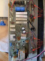
Thanks for the replies, but I'm still confused about this 22 ohm resistor on the PCB. I should be reading +37V at the point outlined in the below picture, right (if the circuit is operating correctly)? If so, I don't see where this resistor is on the SCH...
Attachments

Well, no. I can't see exactly where the bottom .68 ohm resistor goes, but I think it is to that black wire that goes to the emitter of the bottom output transistor. So the other end of the .68 ohm resistor goes to ground. Which is where the schematic diagram says the bottom of the 22 ohm resistor goes. You said earlier that point is .08 v to ground. Which indicates a small resistance problem between that point and the point where you have your meter negative installed.
I'm really much more interested in whether the collector of the top two output transistors is at zero volts, which is where you reported the plus of the speaker cap is. If so, that explains why the light bulb is bright. If on the other hand you have misidentified the plus of the speaker cap as the speaker end, that is much less damaging.
I'm really much more interested in whether the collector of the top two output transistors is at zero volts, which is where you reported the plus of the speaker cap is. If so, that explains why the light bulb is bright. If on the other hand you have misidentified the plus of the speaker cap as the speaker end, that is much less damaging.
Last edited:
If that place where the arrow is pointing is connected to the + side of that 1000 uf cap, then it should be at half the supply voltage. If that is true, the 22 ohm resistor in question is probably in series with that 0.1 uf box cap going to ground. That would be the zobel network. Doesn’t show one on the schematic, but might have been added if there were oscillation problems without one.

I'm much more concerned about the middle of the amp, the emitters of the two output transistor connected via collector to + supply, being grounded. Instead of connected to the speaker. If that point is grounded the current will be as much as the light bulb will allow to flow.
I suggest to try to identify which two transistors have their collectors connected to the + supply. The emitters of those two power transistors will go through .68 ohm resistor to the plus end of the speaker cap. Then with power on check what voltage is on those collectors. Post 41 states the plus end of the speaker cap is at zero volts with power on. Extremely wrong.
Last edited:
I believe the bottom two transistors on the picture below should have their collectors connected to the +supply. Please correct me if I'm mistaken. This is why I am confused about the 22ohm resistor, as it is connected to one leg of the emitter resistors of the bottom two transistors in my picture (as you can see by following the black wires).
Perhaps the black wires are misconnected? Or one of the orange circular capacitors has shorted?
Perhaps the black wires are misconnected? Or one of the orange circular capacitors has shorted?
Attachments
Last edited:
Did you verify with the ohms scale of a dvm that the collectors of the two bottom transistors go the plus of the mains cap and the + of the bridge rectifier?
At this point assuming anything is a waste of time. This amp has been touched by many previous owners, and a wiring error of this magnitude could cause the extremely wrong reading you got on the + of the speaker cap in post 41. The wires to the output transistors are hand installed by the repairman and could be wrong.
With power off, mains cap discharged, and speaker cap discharged, I would buzz (verify) the wiring diagram of all 4 output transistors, their connection to the emitter resistors, connection to power supply, connection to speaker. You buzz a network by making a copy, then coloring in the wires in pencil as you buzz them one by one. Most dvm have a beeper on the diode scale for <10 ohms.
If wiring is correct, I would mark which emitter resistors were the upper (close to speaker cap) and which the lower (close to ground). I would mark the output transistors, which 2 were connected to +74 upper, and which two were connected to speaker cap & ground, lower. Which may be opposite of their position in the picture, as you say.
I would then measure the voltage power on of the collector of the top two (close to 74 v, not upper in the picture) output transistors.
Only after that would I worry about idle current of the output transistors, and or state of the 22 ohm resistor. Wgski is probably right about the zobel network, they got popular about 1970. Zobel networks prevent warrenty calls caused by stupid speaker loads, or RF transmission by CB/Police/fire radios that don't occur in the lab where these amps were designed. Which warrenty calls cost more money than the resistor+cap costs.
Whether the interstage transformer is shorted or not is another major issue that can come after the wiring of output transistors is resolved.
Last edited:
The voltage across those emitter resistors is too high. And it is also not the same fir the top and bottom transistors. Somewhere there is a sneak path for current happening - just need to find it. If you short the bias diodes, the output transistors *should stop conducting*. If they don’t, that might point to where the problem is.
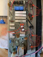
Performed a buzz check as indianajo recommended; wiring looks good (see first picture). I did notice the ground from the output speaker jack was not great, so I tightened up the jack nut. Now I have a solid connection from the negative of the cap can to the chassis ground.
Unfortunately, I still had the same readings (~+32.6 VDC at the positive of the speaker can, ~0 VDC at the positive of the 1000uf capacitor, DBT lit).
I jumped the diodes as wg_ski recommended (see second picture). This bumped the + voltage to ~+52.4 VDC at the positive of the cap can, but the positive of the 1000uf capacitor remained at 0VDC. The dim bult tester was noticeably dimmer with the diodes jumped.
Should I remove the driver transformer and check its windings next?
Attachments
I would pull the two transistors that the collectors are reading zero volts. You've verified that the collectors of those go to the plus of the speaker cap, I believe your check marks indicate. Those are the top two in the picture, correct?
If the voltage at that point (collectors, plus of speaker cap) then goes up, one of the two transistors was installed wrong, or one is shorted C-E. Such transistors short may not show up at 2 v of meter diode scale, but may on a current check from a 12 v power supply through a 47k resistors. I>>12/47000, transistor leaks C-E. Plus on npn is the collector, minus is the emitter. Base is open for Iceo test.
It is also possible that the speaker cap is shorted. If collector voltage stays zero after transistors pulled, pull one end of the speaker cap.
t know how those TO3 transistor sockets work, never owned one. But one could be defective if collector voltage still zero after transistors & speaker cap pulled loose.
A fourth possibility is that a bad solder joint or wiring error is preventing + voltage getting from emitters of top two transistors (lower in picture) getting to collectors of bottom two transistors & + of speaker cap.
A fifth possibility is that a shorted 470 uf e-cap or diode, or shorted winding of the interstage transformer, is preventing the upper transistors (lower in picture) from leaking current to the collector of the lower ones. They are supposed to leak, it is what makes the stage class AB instead of class B.
Last edited:
Thanks indianajo. I pulled the two transistors (whose collectors attach to the +37V rail) and the voltages improved; see picture.
Forgive my ignorance, but I'm not sure I followed how to test the transistors with a power supply (instead of a dmm). Can you point me to a how-to guide?
Checked with diode test again; both remove transistors show a ~.53 VDC drop from base to emitter and open from emitter to base.
Forgive my ignorance, but I'm not sure I followed how to test the transistors with a power supply (instead of a dmm). Can you point me to a how-to guide?
Checked with diode test again; both remove transistors show a ~.53 VDC drop from base to emitter and open from emitter to base.
Attachments
Last edited:
- Home
- Amplifiers
- Solid State
- Peavey PA-200 Powerup With Dim Bulb Tester and Variac