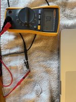
It's a test I made up. DVM have a milliamps scale, so it is cheap. I have a 12 v battery charger I use on car batteries, so I use that. (other voltages over 2 may also be useful if you have an old wall transformer for example. up to 30 v on 2n3055 class transistors) The PV-1.3k output transistors were reading okay on the DVM diode scale, but were exploding one by one as I put resistance limited power to them. So series connect the plus of the 12 v power supply through a resistor (4.7 k or higher) to the collector of the npn transistor. Connect the emitter of the transistor to the plus of the DVM on 200 ma scale. Connect the negative of the meter to negative of the power supply. Takes 3 alligator clip leads. If current is negligable on 200 ma scale, try 2 ma, then 200 ua scales. If current is >V/R, then the transistor is leaking and should be replaced.
BTW I put a x000 uf capacitor across the 12 v battery charger to make the current coming out smoother DC instead of pulsing full wave rectified DC.
BTW I put a x000 uf capacitor across the 12 v battery charger to make the current coming out smoother DC instead of pulsing full wave rectified DC.
Well, no. The video is checking that the transistor will turn on, ie the wires are not burnt intwo between the case & die.Perhaps I should perform this test?
You have a problem with the transistor leaking too badly, so that proves the wires are still good between the case & die.
BTW you did do the DVM diode scale backwards on the b-e and c-e to prove it was holding off 2 volts? Should read ---- or 9999 backwards and 450 to 700 forwards.
This current test is just for transistors that hold off 2 volts and leak at 12 volts or whatever test voltage you have got. My transistors that were leaking at 12 v were the ones that were damaged and were blowing the tops off one by one. Inspection of new parts should be done at a voltage of at least a half of the rated Vceo. Vceo of 2n3055 is 60 volts. Voltages over 24 are dangerous and should strictly follow the one hand at a time rule.
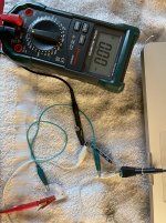
I performed the test shown in this video and found that one transistor shows a ~18.4 Mohm resistance between emitter and collector, while the other shows an open circuit (emitter-collector resistance dropped on both transistors when base was shorted to collector). Does this mean one of the transistors is bad?
Attachments
If resistance on both transistors dropped when base shorted to collector, that proves they will turn on. That doesn't prove that they will not leak badly at 37 volts, or even 12 v.
18.4 megohms is not going to cause the speaker cap to drop to zero volts. Find out how many megohms at a higher voltage. Or, as pro shops do, replace the two transistors without thinking too much about it. Just leaving out the 18.4 megohm one and powering up the other one might tell you something - like only that one leaks too much.
18.4 megohms is not going to cause the speaker cap to drop to zero volts. Find out how many megohms at a higher voltage. Or, as pro shops do, replace the two transistors without thinking too much about it. Just leaving out the 18.4 megohm one and powering up the other one might tell you something - like only that one leaks too much.
Resistance tests are useless, do a diode test.
Maximum value displayable by that DMM is 20M, actually 19.99M, so two very close values, say 18M4 and 20M1 ,within less than 10% from each other will actually be displayed very differently, exactly like you found.
Showing that a resistance test is useless there, except in the grossest of failures, where silicon melted and a gob of metal is shorting everything.
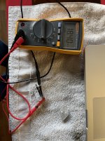
Well, no, zero means the transistor doesn't leak under 12 volts. Test your hookup by measuring leakage without the transistors, just the clips touching each other. That should show 1.2 ma and you're using the meter right. If not, amps fuse is probably blown in the meter. They often are.
Next possibility is collector of one socket is touching something grounded (heat sink?) when the transistors are installed. This is a mechanical problem. Is heat sink grounded?
Next possibility is collector of one socket is touching something grounded (heat sink?) when the transistors are installed. This is a mechanical problem. Is heat sink grounded?
Confirmed ~1.2 ma on meter when touching leads together (no transistor).
Sorry, which heat sink are you referring to? The collector pins of the TO3 sockets?
Sorry, which heat sink are you referring to? The collector pins of the TO3 sockets?
Good. that proves the current test was valid, the meter is working, and transistors hold off 12 v c-e.
The output transistor sockets are mounted on a metal bar, that carries away the heat. That metal bar may be grounded, although on some later peavey products they used plastic washers to keep the heat sink isolated from case ground. Check that. Check next if collectors of either socket connected to metal bar (0 ohms) without the transistors, before putting transistors in them.
The output transistor sockets are mounted on a metal bar, that carries away the heat. That metal bar may be grounded, although on some later peavey products they used plastic washers to keep the heat sink isolated from case ground. Check that. Check next if collectors of either socket connected to metal bar (0 ohms) without the transistors, before putting transistors in them.
The sockets are mounted on the rear plate of the amp (what I've been calling chassis ground), but none of the collectors of the TO3 sockets are continuous to this plate with and w/o transistors installed. Measuring resistance between TO3 socket collectors and chassis ground shows about 400 ohms of resistance (increasing by about 50 ohms a second).
Well, something caused the collectors of the lower two output transistors to go to 0 volts. Increasing meter resistance means you are charging up a capacitor someplace, probably the power supply.
That current from emitters of upper transistors is going somewhere. I suppose now confirm emitters of upper two transistors are at 1/2 power supply voltage, or more (if a bad solder joint) then confirm that voltage through the emitter resistors, then through the circuit board to the plus of the speaker cap and the collectors of the lower two output transistors. That voltage has to go somewhere, either blocked by a bad solder joint, or blown upper emitter resistors, or current sucked off to ground by a short somewhere.
That current from emitters of upper transistors is going somewhere. I suppose now confirm emitters of upper two transistors are at 1/2 power supply voltage, or more (if a bad solder joint) then confirm that voltage through the emitter resistors, then through the circuit board to the plus of the speaker cap and the collectors of the lower two output transistors. That voltage has to go somewhere, either blocked by a bad solder joint, or blown upper emitter resistors, or current sucked off to ground by a short somewhere.
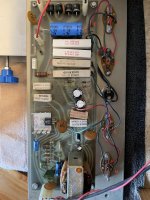
the upper (in voltage & on schematic) transistor emitters are K & M. I think I is upper end one emitter resistor, the other is not labeled. The lower end of those resistors G & H should be same voltage as D & A. I believe the positive end of the speaker capacitor is not labeled, but you've reported it to be at 0 volts, same as D & A. F is the speaker end of the speaker cap, right? You should know now after buzzing the circuit. Go with your buzz experience, not my guesses off a picture 1.5"x3" from 1000 miles away.
Note during this test the bias diodes should not be shorted. b-e of both upper transistors (voltage) should be about .6 v. The 1k 5 w resistor provides this idle bias current through the secondary of the insterstage transformer.
Note during this test the bias diodes should not be shorted. b-e of both upper transistors (voltage) should be about .6 v. The 1k 5 w resistor provides this idle bias current through the secondary of the insterstage transformer.
Last edited:
Here are the measured voltages based on the picture in post #72. All voltages are DC with the negative of the DVM attached to chassis ground. I also measure +31.8 VDC across cap can. Any clues?
A. +.112
B. +.077
C. +.077
D. +.113
E. +.116
F. +.116
G. +.118
H. +.118
I. +.195
J. +31.5
K. +.197
L. +31.4
M. +.197
A. +.112
B. +.077
C. +.077
D. +.113
E. +.116
F. +.116
G. +.118
H. +.118
I. +.195
J. +31.5
K. +.197
L. +31.4
M. +.197
Last edited:
So you have .195-.118 v drop across the upper emitter resistors, or .130 amps. that is a lot of idle bias current coming out of the upper two transistors. And it is going across the two lower output transistors c-e with only .118 volt drop? Those two lower output transistors must have lots of current into the base lead, since you proved that they weren't shorted. Or the speaker cap is shorted. You have measured 31.8 "across" the speaker cap, but still haven't told me what the voltage on the left end is. The end that appears to say "+" in silver on the board next to it.
If the 31.8 refers to the main supply cap, please say so.
I'd check the speaker cap not shorted by pulling one lead. If that doesn't pull the voltage of the lower collectors up to 1/2 the rail voltage, or more, I'd pull one end of the .02 uf cap that supplies drive current to the lower transistor bases. Maybe it is shorted.
Really after buzzing it out, I would have marked the board with a sharpie with "U" and "L" on the upper and lower emitter resistors, and by the associated output transistors. U meaning to me, close to the upper supply rail, and "L" meaning close to ground rail. U & L having nothing to do with the position in the picture. Also marking which end of the speaker cap is plus, since it doesn't show in the picture except for the silver marking on the board near the left end. Whereas the right end has the pinch that usually goes with the plus end of an axial electrolytic cap. After buzzing you should know which end of the speaker cap goes to lower transistor collectors, and which end goes to the speaker terminal. From 1000 miles away, I don't.
Last edited:
The 31.8 I measured was across the 3500 uf cap (what I'm calling the "cap can"). The "speaker cap" is the 1000uf cap, right? I'll mark the board and check the voltage on the left end of the 1000uf cap.

You have already measured .1 v across the two lower emitter resistors. That is 140 ma. So the bias current from the top two transmitters is going through the two lower transistors, instead of out the socket to the heat sink.
I'd disconnect the base lead to the transistors sockets of the two lower transistors, to see if current is leaking in the base lead and causing the c-e leakage. If that doesn't pull the two upper transmitter emitters to 37 volts, replace the two lower output transistors.
If pulling the base lead does fix the low voltage at + of speaker cap, pull the .02 uf cap. If that doesn't fix it, you need to replace the interstage transformer with an AX6 or TGM8 board with 4 more $1 transistors and 3 $1 heat sinks.
I'd use MJ15015 which have superior Vceo to 2n3055a, or MJ21194, which has both superior Vceo & soa current rating. MJ21194 is usually in stock everywhere and is relatively inexpensive. I've gotten MJ15015 for $1.40 but that may have been a special deal. The box from an authorized distributor like newark or digikey will be $8 minimum. Don't use newark in canada to avoid UPS loan origination fee.
Last edited:
Measured ~.08VDC at the negative of the 1000uf speaker cap. I'll try disconnecting the base lead of the lower two transistors next and check upper transmitter emitter voltage.
Forgive my ignorance again, but how can the bias current of the top two transistors flow out of the socket to the heat sink? The transistor sockets are electrically isolated from the heat sink with a plastic pad.
And the .02 cap you are referring to in the one designated in the attache picture, correct? Between the + rail and upper transmitter bases.
Attachments

Misassembly or failure of a mica pad frequently causes TO3 collectors ton contact a grounded heat sink. I'd reconfirm the voltages top & bottom of the emitter resistors to the lower output transistors, as the .08 at the lower end of speaker cap indicates a slight ground problem.
If the drop across the lower emitter resistors indicates 140 ma, and you have 130 ma indicated across upper emitter resistors, that kind of leaves out the possibility of the current leaking out of the collectors of the lower output transistors to ground directly through the heat sink.
I really wouldn't worry about the .02 uf cap until I had disconnected the base lead to the lower output transistors and proven that drives the emitters of the upper transistors to a higher voltage. Output transistors fail so often that most shops replace them first without doing any diagnostic work. We amateurs don't have a big stock room full of transistors, so measuring some things is a lot easier than ordering output transistors first thing. We don't even know what continent you are one to suggest a suitable authorized distributor.
I can't see the board well enough to determine that the cap you point to connects to the bases of the lower output transistors. It is near the green wire that connects to the bases of the upper transistors, but that doesn't mean it is connected. Verify connection with the beeper. Failure of this capacitor would be really rare, but replaciing that is much cheaper than replacing the interstage transformer (which has a brown spot).
If the board varies from the schematic in what provides plus current to the bases of the lower output transistors, check that with your eyes & beeper. The schematic we're working off of doesn't even have the same name as the product you are working on.
Last edited:
- Home
- Amplifiers
- Solid State
- Peavey PA-200 Powerup With Dim Bulb Tester and Variac