I'm not sure if it was discussed before. If i want more gain than 65dB, can R14 go lower than 300 ohm ? say R14 = 100 ohm ?
Or should I keep R14 = 300 ohm and start to increase R15 ?
I have 0.25 mV MC cart and low powered amp with low efficient speaker. 65 dB full gain from Pearl 2 is still not quite enough.
Do you see any issues with going higher than 65 db for Pearl 2 phono stage ?
Thanks guys,
Tom
Personally I'd look at my amp and speakers if 65db wasn't enough from the phono stage.
Thanks for the reply Mark. I have finished Pearl 2 and enjoy it for 2 years now. It's very musical but i feel like the power and punch of music is lacking compared to my digital sources in the same amp/Dac/speaker configuration. The digital music is always louder and larger in soundstage. I came back to the Pearl thread and revisited some of the mods that could enhance my Pearl 2 further.
Thanks,
Tom
Thanks,
Tom
Personally I'd look at my amp and speakers if 65db wasn't enough from the phono stage.
Thanks for the reply Mark. I have finished Pearl 2 and enjoy it for 2 years now. It's very musical but i feel like the power and punch of music is lacking compared to my digital sources in the same amp/Dac/speaker configuration. The digital music is always louder and larger in soundstage. I came back to the Pearl thread and revisited some of the mods that could enhance my Pearl 2 further.
Thanks,
Tom
I'm not sure what the issue is, I run cartridges in that range of output and have plenty of gain compared to digital sources. Maybe check some voltages?
Attachments
Strange voltage at P1 zero volt test point. Please help!
Hello there,
Thank you in advance for your expertise.
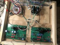
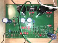
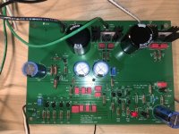
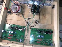
I have been studying this Pearl 2 phono stage project for quite a while, looked at almost all of you guys’ discussions, detailed instructions, and beautiful pictures. Finally, I plunged myself into this diy project and encountered very strange (probably serious?) problem. I followed Jim’s advice and got Antec AS0522 transformer. Then, through 2 full wave bridge rectifiers, two banks of 2 x 10,000 uF caps (total of 40,000uF), 2 bleeder 22kOhms resisters, and two 0.47 ohm PI resistors, I got + 28.8 V and + 29.3 V unregulated and about the same voltages for regulated.
Then, when I checked the P1 test point (the pad that has “set P1 for 0 volts DC), I got negative (-) 23.4 volts (yes, volts and NOT mV). Turning the P1 trimmer dial did not change the above voltage at the P1 test point.
The same high voltage reading at P1 test point was also noted at the other PCB as well. Adjusting P1 trimmer on the second board didn’t not change the voltage at all. As far as the resistors and capacitors, I did check there values carefully prior to stuffing the boards. I didn’t check the transistors prior to assembly however.
My questions to you:
1. Did I install the P1 trimmer wrong? I did order a “similar Value” 5K Bourn trimmer with 3 pins in a straight line (instead of the one with the center pin offset a little bit). Both Mouser and Digi-Key didn’t have the trimmer with central offset pin at that time. Moreover, I thought these trimmers were interchangeable, just bend the center pin over a little bit to fit. Maybe I am wrong.
2. What else should I check to troubleshoot this problem?
3. Did I damage other components (i.e. the chip set) by having such high negative voltage at this point?
4. Were the regulated and unregulated DC voltages too low for the transistors to function properly? How can I increase these voltages?
Thanks a million. I will post some pictures of my boards and PSU.
Hello there,
Thank you in advance for your expertise.
I have been studying this Pearl 2 phono stage project for quite a while, looked at almost all of you guys’ discussions, detailed instructions, and beautiful pictures. Finally, I plunged myself into this diy project and encountered very strange (probably serious?) problem. I followed Jim’s advice and got Antec AS0522 transformer. Then, through 2 full wave bridge rectifiers, two banks of 2 x 10,000 uF caps (total of 40,000uF), 2 bleeder 22kOhms resisters, and two 0.47 ohm PI resistors, I got + 28.8 V and + 29.3 V unregulated and about the same voltages for regulated.
Then, when I checked the P1 test point (the pad that has “set P1 for 0 volts DC), I got negative (-) 23.4 volts (yes, volts and NOT mV). Turning the P1 trimmer dial did not change the above voltage at the P1 test point.
The same high voltage reading at P1 test point was also noted at the other PCB as well. Adjusting P1 trimmer on the second board didn’t not change the voltage at all. As far as the resistors and capacitors, I did check there values carefully prior to stuffing the boards. I didn’t check the transistors prior to assembly however.
My questions to you:
1. Did I install the P1 trimmer wrong? I did order a “similar Value” 5K Bourn trimmer with 3 pins in a straight line (instead of the one with the center pin offset a little bit). Both Mouser and Digi-Key didn’t have the trimmer with central offset pin at that time. Moreover, I thought these trimmers were interchangeable, just bend the center pin over a little bit to fit. Maybe I am wrong.
2. What else should I check to troubleshoot this problem?
3. Did I damage other components (i.e. the chip set) by having such high negative voltage at this point?
4. Were the regulated and unregulated DC voltages too low for the transistors to function properly? How can I increase these voltages?
Thanks a million. I will post some pictures of my boards and PSU.
Attachments
Are SJ74 BL92 transistors interchangeable with SK370 transistors?
Hello Gents,
I saw a post on this forum dated a few years ago regarding the matched transistors shipped with the Pearl 2 boards from PassDiy website.
I got 2 sets of J74 BL92c (12 in total), which were installed and soldered into the 2 boards shown above.
Are J74 BL92 transistors interchangeable with SK370 transistors? Their datasheets show quite a big difference in polarity and voltages.
Could this be the source of my problem? Wild voltages at P1?
Quan
Yikes! They are most definitely not interchangeable. 🙁
It seems you were shipped the wrong jfets.
2sk170 can be used in place of 2sk370.
This is rather unfortunate. I expect the jfets you got are
very well matched (I know mine were) but, alas, the wrong
part.
Please contact passdiy and see if they can send some replacements.
In any case, I suggest you carefully desolder the 2sj74 and then
test them to see if they're still ok.
I hope you have this resolved soon.
Last edited:
US $9.62 32%OFF | Lusya SUQIYA-Sigma79 Series LDO Low Noise Step-Down Linear Regulated Power Supply Module T0703
Lusya SUQIYA Sigma79 Series LDO Low Noise Step Down Linear Regulated Power Supply Module T0703|Amplifier| - AliExpress
US $9.33 34%OFF | Lusya SUQIYA-Sigma78 Series LDO Low Noise Step-Down Linear Regulated Power Supply Module T0703
Lusya SUQIYA Sigma78 Series LDO Low Noise Step Down Linear Regulated Power Supply Module T0703|Amplifier| - AliExpress
I haven't started mine.. Still collecting parts.. But I'm going to gib Dis regulator a go... Look schweet
purchasing:
S78 is a positive voltage
S79 is a negative voltage
Sigma78 and Sigma79 are LDO-type DC regulators with 4uV ripple;
Used to directly upgrade the conventional LM78XX and LM79XX; the function pins are exactly the same.
Sigma78 is based on the Ti-TPS7A 4701RGW ultra-low noise positive LDO regulator developed for applications;
Sigma79 is based on the Ti-TPS7A 3301RGW negative LDO regulator developed for applications;
The maximum input voltage does not exceed 35V, and the maximum output current is 1A;
In practical applications, it is recommended that the input and output voltage difference be not less than 0.5V.
The application current does not exceed 0.7A (very careful attention to heat dissipation, especially when the high voltage is low
I bought the njr too will compare.
I'm using these regulators. Not from Ali but AMB audio, and I had to solder them myself (resistors and capacitors) which is a pain in the a** with these small smd parts. I kept the voltage a little below 24V to have some margin for the 25V output capacitor.
No, just the sigma 78 and 79 boards. Those from AMB come with only the regulator soldered on. The rest of the parts you can choose yourself to make any output voltage within the limits. I have them somewhere between 23.6 and 24 V. Exact outcome depends a bit on the real value of the resistors used.
I can't really tell. My latest build on the official boards is a little quieter than my previous build on perfboard. But there could be many reasons for that. Anyway, it's an easy solution to add these low noise regulators and I feel I have now nice and clean power with little effort. I would be interested if someone could measure the Pearl with stock PSU and 7x24 regulators vs all kinds of advanced PSU's to see if there is any measurable difference.
If you are interested in such measurements, I’d suggest it being a really good excuse to get some equipment (a USB sound cars and REW software would be a great place to start) and make some measurements. 
;-) My Pearl 2 is now finished and installed safely in it s cabinet. Don't want to take it out again and start replacing parts... Maybe when I'm retired one day. I'd also like to know if there's any measurable difference between Vishay resistors and something like Xicons that Hagerman uses in the Bugle (22 cents / 10 pieces). A Pearl with cheap (but good and matched) parts versus a boutique Pearl so to say.
Modern production has made the inexpensive resistors (and other components) very, very good. IMO, boutique parts mainly succeed in making your wallet lighter.
Is there any voltage references for this phono? My mate has it, but it doesn't work, it distorts and speaker cones are going in-out 'like crazy', without any input signal. JFETs are 2SK170 with 77mV through 10R source resistors.
Thanks
Edit: found it, it was at page 299 😀
Thanks
Edit: found it, it was at page 299 😀
Last edited:
I would be interested if someone could measure the Pearl with stock PSU and 7x24 regulators vs all kinds of advanced PSU's to see if there is any measurable difference.
I measured the stock Pearl w LM regulators AND the Jung/Didden regulator set for 24V -- there was no difference in the output noise. If I recall correctly, I used an AT MM cartridge loaded with 47k. (The 47k itself is essentially shunted by the low impedance of the cartridge, and little current flows from the gate of the JFETs).
The source resistors of the JFETs are, perhaps, the largest noise source (other than the cartridge itself), and here the value was (apparently) chosen for both the operating point of the devices AND ease of dealing with JFETS which aren't perfectly matched. There's 6-7mA flowing through each source resistor. The input noise of the JFET stage is probably less than a nanoVolt/RtHz.
Once the needle hits the record surface, you will find it impossible to hear a difference.
Modern production has made the inexpensive resistors (and other components) very, very good. IMO, boutique parts mainly succeed in making your wallet lighter.
Very true, and not necessary better than rn55
I'll stick to Dale mainly..
- Home
- Amplifiers
- Pass Labs
- Pearl Two