Yup, that did the trick. Now I have +-33VDC rails.
I started adjusting the trimpot, but it is proving harder than I thought. It comes to about 14V and then suddenly goes in the other direction. Is this normal?
I do not have the tools to determine whether the circuit is oscillating or not.
Help appreciated!
I started adjusting the trimpot, but it is proving harder than I thought. It comes to about 14V and then suddenly goes in the other direction. Is this normal?
I do not have the tools to determine whether the circuit is oscillating or not.
Help appreciated!
Yup, that did the trick. Now I have +-33VDC rails.
I started adjusting the trimpot, but it is proving harder than I thought. It comes to about 14V and then suddenly goes in the other direction. Is this normal?
I do not have the tools to determine whether the circuit is oscillating or not.
Help appreciated!
Multi turn trimpot is required to adjust without hassle.
Try to remove C7 if you dropped it in, and see if it works as for Hesener 🙂
Best,
nAr
Yes, its a multiturn pot.
Instead of removing C7, first I tried putting in additional 5pf for C15 (or Cx) and it worked, but the offset wasn't stable. It stayed at 0mV for a while then went back to large values. Next, I tried 10pF at C15 and this worked. It is now stable at 0mV.
Not sure if this is the right thing to do though. If this is not a feasible option, I can consider removing C7.
Yes, its a multiturn pot.
Instead of removing C7, first I tried putting in additional 5pf for C15 (or Cx) and it worked, but the offset wasn't stable. It stayed at 0mV for a while then went back to large values. Next, I tried 10pF at C15 and this worked. It is now stable at 0mV.
Not sure if this is the right thing to do though. If this is not a feasible option, I can consider removing C7.
Try removing C7 and your added extra capacitance on R feedback;
Because extra C on feedback R will limit the bandwidth and rollen square waves;
Then if offset is stable, preferred solution;
If not stable, go back to the previous solution you found 😎
Best,
nAr
Last edited:
After removing C7, the zero offset point is easier to find. However, the offset is not stable. It goes positive and negative up to 1V. Most of the time it is between +-500mV... which is still quite high I believe.
I did not install the input cap for cartridge loading. Do you think this may be having an effect?
Tried playing music through it and it comes out distorted. The LED also flexes with the music.
I did not install the input cap for cartridge loading. Do you think this may be having an effect?
Tried playing music through it and it comes out distorted. The LED also flexes with the music.
Last edited:
After removing C7, the zero offset point is easier to find. However, the offset is not stable. It goes positive and negative up to 1V. Most of the time it is between +-500mV... which is still quite high I believe.
Yes, it seems too high not stable enough. Sorry to hear. Did also you remove the extra capacitance on feedback at the same time ?
I did not install the input cap for cartridge loading. Do you think this may be having an effect?
You should try to ground inputs to set the zero offset
Tried playing music through it and it comes out distorted. The LED also flexes with the music.
If distorted, verify your input swing; combined to gain settings you chose, a 1V-2V output swing is acceptable, but more will give you too much distortion. If you use a cartridge that has more than 2mV output, then you should think about reducing the gain of the 2nd stage. Remember Pearll II suits better low level output delicate MC cartridges, but can be tweaked to feed MM as usual, with 2nd stage gain adjustment.
The led should not flex with the music, and it clearly indicates a problem here. Maybe oscillation, or too high distorted output swing caused by too high input level. Also, try to get back to your previous capacitor combination to see if it helps.
Best,
nAr
Yes, I removed the 10pf cap I had installed at C15 (Cx). Let me try with grounded inputs.
After the regulators, I get a solid +-24VDC, which is good. Also, all the problems are identical in both channels.
I'm using a Grado black which has 5mV output, probably too much. But this would mean overloading the first stage, wouldn't it? The second stage sees a filtered signal which shouldn't be a problem.
I had a DL103, but it is 8,000 miles away from me right now 🙁
Last edited:
Approx. gain values for feeback resistor values ( 2nd stage )
100k about 40dB (original)
50k about 33dB
33k about 30,4dB
150k about 43,5dB
Capacitor in parallel with feeback resistor will logically need to be increased for lower gain settings than the 100k original value
nAr
Yes, I removed the 10pf cap I had installed at C15 (Cx). Let me try with grounded inputs.
After the regulators, I get a solid +-24VDC, which is good. Also, all the problems are identical in both channels.
I'm using a Grado black which has 5mV output, probably too much. But this would mean overloading the first stage, wouldn't it? The second stage sees a filtered signal which shouldn't be a problem.
I had a DL103, but it is 8,000 miles away from me right now 🙁
From my own experience with my MC3 turbo from Ortofon (3,3 mV), with your Grado I think you definitely need to adjust the gain of the 2nd stage lower, to about 30 dB ( 33k RFeedback, or 100k X 3 in parallel to test value ) to get "correct" output levels vs bias and psu voltages of the whole 2nd stage.
1st stage is unlikely to saturate in normal conditions even with a MM plugged in. Exception is if the 1st stage isn't properly polarized, e.g. error or mismatched fets or too low IDSS maybe (thus nor enough current).
Can you do a checkup of the different voltages you can pick in the 1st stage ?
Best,
nAr
Last edited:
By how much did you raise the capacitor for 33k or 30db gain setting?
I still can't get a stable bias with grounded inputs.I'm thinking about going back to my earlier scheme, with C7 back in and adding Cx at 10 pf.
I still can't get a stable bias with grounded inputs.I'm thinking about going back to my earlier scheme, with C7 back in and adding Cx at 10 pf.
Hi, my cartridge (Clearaudio Talismann) has 0.5mV output so the gain setting as in the original schematic is just right. For lower gain (and lower R16), the value of C9//C15 will have to be increased. The values in the schematic give a corner frequency of about 318kHz. The oscillations will depend on the phase margin you have at the high frequencies, where the gain of the output stage is still higher than 1.
Sounds like the gm's of the MOSFETs are pretty high, and the current sources are pretty good too so the open loop gain might be higher than expected. With a gm of 20mS at the drain current chosen (estimated from the diagramin the datasheet9, and the maximum load of 100k (R18), ignoring the finite output impedance of the current source for a moment, the gain of that stage is a whopping 66dB.... and that may be higher, depending on the device. Add to this the gain of the diffamp (gm of around 15ms, again from the diagram of the datasheet, load resistance lets say 3k, times 2) gives another 40dB, so there is a LOT of gain around this loop. no wonder it is not super-easy to get stable...
When I had the problem, I also noticed the brightness of the LED fluctuating in some cases, that can only be caused by high base currents through the current source NPNs. Now, how can that happen? The only reason I could figure out was a large voltage swing on the output, that would lead to recharging the output cap through the base and the load resistor (in my case, a 10k pot).
Would be interesting to see what will fix your oscillation problem, let us know!
best regards
Thanks for all your help Nar and Hesener.
I will check all the voltages with reference to Algar's post a few pages back. It looks like its the second stage that has problems.
With 33k instead of 100k, what capacitance value do you anticipate? Should it be increased 3 times?
I will check all the voltages with reference to Algar's post a few pages back. It looks like its the second stage that has problems.
With 33k instead of 100k, what capacitance value do you anticipate? Should it be increased 3 times?
Well, something new has started to happen. In one channel, the LED has taken to smoking. I replaced it once and then R29 started smoking along with the mosfet. I replaced the mosfet and R29 and now again the LED is smoking. Is it worth replacing Q10 and Q11 also? They have not shown smoke yet. What other parts could be damaged?
Up until now, both channels were showing the same symptoms, which to me meant that there was something wrong with the circuit. Now, with this one channel perhaps something else is going wrong.
Up until now, both channels were showing the same symptoms, which to me meant that there was something wrong with the circuit. Now, with this one channel perhaps something else is going wrong.
Have you checked R25, and the connections on the LED side? With the ground plane pretty much everywhere, it is quite easy to create shortcuts to ground. best to check with a resistance meter all the nodes in the circuit before powering up. I had similar trouble when using a solder pump, that left little particles of solder on the PCB, that would create shortcuts. Only way is to (visually) check carefully after soldering, and also measure with a DMM. Definitely the parts that have smoked should be replaced.
Most DMMs nowadays can also measure diode voltage drop, and from time to time when playing with the amp I would check the base-emitter junction of Q10 and Q11 just to make sure.... it also worked with the LEDs, allowing me to select them for forward voltage as well (not sure it matters though....)
Just measured across R25, and the readings were 4.71k in both polarities, and on both channels. From the bases of Q10 and Q11 to ground, I measured 4.93k, again both polarities and both channels. The base-emitter forward voltage on Q10 and Q11 was 664mV (give or take a couple mV).
On the value of C9, increasing 3x (so, 15pF) is a good start. Do you have a way to measure the frequency response of the second stage?
hope that helps....
This is the good procedure. Until you find the error 🙂Have you checked R25, and the connections on the LED side? With the ground plane pretty much everywhere, it is quite easy to create shortcuts to ground. best to check with a resistance meter all the nodes in the circuit before powering up. I had similar trouble when using a solder pump, that left little particles of solder on the PCB, that would create shortcuts. Only way is to (visually) check carefully after soldering, and also measure with a DMM. Definitely the parts that have smoked should be replaced.
It doesn't really matter, you should in theory find a led that direct V at given current matches the bipolar VBE coupled + the given 1 V drop on the resistor ... 🙂Most DMMs nowadays can also measure diode voltage drop, and from time to time when playing with the amp I would check the base-emitter junction of Q10 and Q11 just to make sure.... it also worked with the LEDs, allowing me to select them for forward voltage as well (not sure it matters though....)
Beware with the diode test function of the DMM, it doesn't reflect the diode direct V in the particular application, as the DMM measures them with fairly low current, e.g. much smaller than the setup.
The R25 defines the bias of the led, VBE on the bipolars give the standard roughly 0,65V value 🙂Just measured across R25, and the readings were 4.71k in both polarities, and on both channels. From the bases of Q10 and Q11 to ground, I measured 4.93k, again both polarities and both channels. The base-emitter forward voltage on Q10 and Q11 was 664mV (give or take a couple mV).
Yes, good way to proceed 🙂 Or input a small amplitude square wave ( 10mV or so) at the 2nd stage input, and watch its shape at the output to adjust C9 value 🙂On the value of C9, increasing 3x (so, 15pF) is a good start. Do you have a way to measure the frequency response of the second stage?
question for wayne....
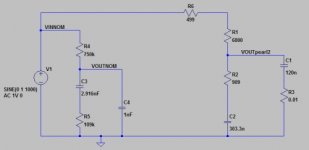
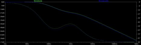
Hi, I have a question: When simulating the RIAA network, I found the response to be about 1dB below the normal curve, for higher frequencies - see simulation circuit and resulting plot attached. As I couldn't find any other frequency-dependent stuff in the circuit (at least not in the interesting frequency range), I was wondering what my oversight is. Remember you put a diagram of RIAA response in the article, that showed very good compliance....
just wondering.... in the simulation I reduced R1 (corresponding to R11 in the Pearl II schematic) to 5600 ohm, and the fit was very good. I also introduced the 22ohm resistor to implement the 3.18us time constant. Listening test is tonight, let's see what happens...
Attachments
Hi, I have a question: When simulating the RIAA network, I found the response to be about 1dB below the normal curve, for higher frequencies - see simulation circuit and resulting plot attached. As I couldn't find any other frequency-dependent stuff in the circuit (at least not in the interesting frequency range), I was wondering what my oversight is. Remember you put a diagram of RIAA response in the article, that showed very good compliance....
just wondering.... in the simulation I reduced R1 (corresponding to R11 in the Pearl II schematic) to 5600 ohm, and the fit was very good. I also introduced the 22ohm resistor to implement the 3.18us time constant. Listening test is tonight, let's see what happens...
We all wait for techies 😉
Best,
nAr
Update, the listening test showed the same tonal balance and warmth in the mids, but the focus and localisation has become better. there seems to be more "air" in the highs, they sound more relaxed.
Difficult to find words for this.... I am not a hifi reviewer and don'T want to become one.... But I do like the sound better now. Recognise that the whole system setup plays a role there. Definitely I need to get going on my tonearm adjustment now, there seem to be a couple things to be improved that I couldnt hear before
ra7, are you up and running?
Update, the listening test showed the same tonal balance and warmth in the mids, but the focus and localisation has become better. there seems to be more "air" in the highs, they sound more relaxed.
Difficult to find words for this.... I am not a hifi reviewer and don'T want to become one.... But I do like the sound better now. Recognise that the whole system setup plays a role there. Definitely I need to get going on my tonearm adjustment now, there seem to be a couple things to be improved that I couldnt hear before
So can you make clear which values you changed ? We still wait for Wayne's explanation of course 🙂
Best,
nAr
Sorry for my oversight, I had changed the values as indicated in my simulation - R11 to 5.6k, and additional 22 Ohm in series with C14/C10/C11.
best regards
best regards
No, I am not up and running. I'm taking a breather. I wasn't expecting this to be difficult to get right and am a little discouraged that it isn't working yet.
Anyway, I'm getting some new soldering tips today and I'll get working on the pcb.... checking for shorts and comparing resistance at different nodes between the two channels.
Thanks for the encouragement guys.
Anyway, I'm getting some new soldering tips today and I'll get working on the pcb.... checking for shorts and comparing resistance at different nodes between the two channels.
Thanks for the encouragement guys.
- Home
- Amplifiers
- Pass Labs
- Pearl Two