Good morning Dirk,I needed around 30 TOSHIBA 2SK209GR off the role to get a very, very closely matched octett.
Greets
Dirk
Thank you very much for your information - let's see how I can ultimately solve this inconvenience. We have a lot more than just one dealer in Germany, I had completely forgotten about Mouser in the meantime.
By the way, I find it very interesting that you, like me, got 8 out of 30. My two quartets fit extremely well, even the individual group members don't differ (hardly). I find that remarkable. Let's see what the Yfs etc. pp. looks like at the operating point - in comparison to the extracted values from the characteristics and the data sheet? A small test amplifier can be set up quickly - but with age you get lazy and tired 😳. But I'm looking forward to the final result 🙂.
Bye,
HBt.

I noticed while shopping for parts that Schurter offers a line of two-stage filtered power entry modules, DD14 series, in the same form factor as the recommended single-stage module DD12.9111.111. They're a a bit more expensive but offer a good increase in RF rejection. Possibly overkill, but can't hurt. I went with 3-103-776 (don't forget the matching fuse drawer 4301.1401, which differs from the fuse drawer p/n for the DD12), and can confirm that it fits the chassis perfectly. Note that Mouser's product page shows the wrong photo for it - the actual product is "style A" per the catalog.
https://www.mouser.com/ProductDetail/Schurter/3-103-776
https://www.mouser.com/ProductDetail/Schurter/4301.1401
https://www.mouser.com/ProductDetail/Schurter/3-103-776
https://www.mouser.com/ProductDetail/Schurter/4301.1401
Hmm. Let's try again:
• Schurter DD14, p/n 3-103-776 (1A, style A, two-stage filter)
• Fuse drawer for 3-103-776
• Schurter DD14, p/n 3-103-776 (1A, style A, two-stage filter)
• Fuse drawer for 3-103-776
Much better. They only show 2 of the input modules available but thousands of the fuse drawers... Move quick.
Fortunately, they are available in multiple current ratings, all of which should work:
• 1A: 3-103-776
• 2A: 3-103-777
• 4A: 3-103-778
• 6A: 3-102-850
• 8A: 3-103-779
• 10A: 3-103-780
I just pasted those from the data sheet so you may want to double check the p/n before you hit the buy button. All of those should be the Standard version, "screw-on A" mounting, non-illuminated, black. There are also medical versions, although they lack the Y caps so filter performance isn't as good.
Hello,
Just for fun here is a photo of 4 2SK209 random soldered on tiny (not by me) adaptor boards. Note the CAT6 conductors soldered to the tiny PCB's by me.
Rolling Jfets not op-amps.
I will post the measurements vs 2SK170.
Thanks DT

Just for fun here is a photo of 4 2SK209 random soldered on tiny (not by me) adaptor boards. Note the CAT6 conductors soldered to the tiny PCB's by me.
Rolling Jfets not op-amps.
I will post the measurements vs 2SK170.
Thanks DT
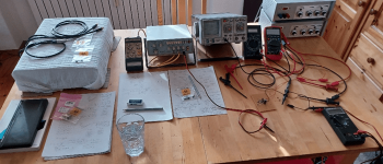
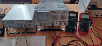
Old school - a bit of nostalgia
My first equipment, a bit dusty - and really, the patina could already be called sand and no longer dust. But that's how I started once, with a Fluke73 (and mine was from the very early 1980s, it cost a lot of money back then - but I wanted a great multimeter' in my pocket).
To cut a long story short, the exciting feeling of the unknown to be explored unfortunately never came back - the distant memory remains with me, but today we are really quite spoiled with our super-duper analyzers ... oh, when I think of the typical smell of the labs back then, fully equipped, the HPs, the Phillips ..!
Well then,
I took a classic look at the jFets - and learned nothing other than that the practical student test confirmed the theoretical principles 100%. From my current perspective, it is not even surprising that all the parameters determined correspond to those from the Toshiba data sheet, even the values extracted from the characteristic curves were confirmed.
Oh how I would love to jump back 40 years and smell the smell of the labs and meet my fantastic lecturers. The people, their immeasurable expertise and the facilities - it must have been a dream.
I reminisce, it doesn't matter - my Toshibas work exactly as they should. It's just a shame that I can only find BLs in my entire stash.
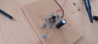
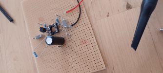
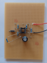
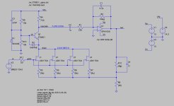
A few pictures for your edification. The test circuits, possibilities and various options are well known. On the left a basic amplifier circuit and on the right the selection on I_DSS. That's all you need, apart from knowing what you are doing there. Unfortunately I didn't have any sleeves for the soldering nails and test points.
What else is missing? The ZTX boys
My first equipment, a bit dusty - and really, the patina could already be called sand and no longer dust. But that's how I started once, with a Fluke73 (and mine was from the very early 1980s, it cost a lot of money back then - but I wanted a great multimeter' in my pocket).
To cut a long story short, the exciting feeling of the unknown to be explored unfortunately never came back - the distant memory remains with me, but today we are really quite spoiled with our super-duper analyzers ... oh, when I think of the typical smell of the labs back then, fully equipped, the HPs, the Phillips ..!
Well then,
I took a classic look at the jFets - and learned nothing other than that the practical student test confirmed the theoretical principles 100%. From my current perspective, it is not even surprising that all the parameters determined correspond to those from the Toshiba data sheet, even the values extracted from the characteristic curves were confirmed.
Oh how I would love to jump back 40 years and smell the smell of the labs and meet my fantastic lecturers. The people, their immeasurable expertise and the facilities - it must have been a dream.
I reminisce, it doesn't matter - my Toshibas work exactly as they should. It's just a shame that I can only find BLs in my entire stash.
A few pictures for your edification. The test circuits, possibilities and various options are well known. On the left a basic amplifier circuit and on the right the selection on I_DSS. That's all you need, apart from knowing what you are doing there. Unfortunately I didn't have any sleeves for the soldering nails and test points.
What else is missing? The ZTX boys
Attachments
Dear Jim,ZTX457 has a better Vearly than the 851, and so was chosen for the capacitor multiplier position (...)
I am familiar with the Early effect and the so-called Early voltage, including what it says - but it's not clicking in my central processing unit at the moment.
Please help me out here with more details and perhaps some data. The aspect with the current availability on the market and the optimal kit supply is of course immediately understandable, but with the calculation value V_early it is not quite so simple.
I'm at a loss right now.
The statement of "better" irritates me, something is missing to understand what you want to say.
Kind regards,
HBt.
🐢
I withdraw my last question or request,
now I know what you said technically unspoken - and you are right, especially with the Pearl3 with its rails of only +15V (to 0 and -15V).
So I have no more questions about the P3, now it's time to implement it.
now I know what you said technically unspoken - and you are right, especially with the Pearl3 with its rails of only +15V (to 0 and -15V).
So I have no more questions about the P3, now it's time to implement it.
I put together a couple of LTspice decks - one for the input stage, and another for the EQ stage. Here they are in case anyone wants to play around with them.
The input stage is using the LSK170A model with a slightly lower source resistor value, which should be pretty close to the 2SK209. There are a pair of diodes and a cap attached to the cascode bias network, which I was messing around with. They can be ignored or deleted. I haven't yet modeled a cartridge impedance, so for the moment it's just a 50Ω source.
The EQ stage may be handy if you're hand matching parts ... let's say out of your batch you got a pair of closely matched caps toward the low end of the tolerance range, and another close pair near the high end, you can try them here first to see which position might work best, and/or if tweaking a resistor value might help compensate.
Attachments
I've previously mentioned a cheap and easy way to do Azimuth, and just tried it out on my rig, easy and very nice resuts! Connect + of 1 channel to + of RCA and the other channel + to the RCA -. Play a mono source with little high frequency and adjust for closest to null. I know this might not be the best method, but for someone without the equipment....
- Home
- Amplifiers
- Pass Labs
- Pearl 3 Burning Amp 2023