Maybe you made the same mistake as many others.
You have probably reversed + and -. The "+" sign at PCB is for the capacitor. Not the LED.
For the LED you should look at the LED-symbol. It has a flat edge which should correspond to the flat edge on LED?
You have probably reversed + and -. The "+" sign at PCB is for the capacitor. Not the LED.
For the LED you should look at the LED-symbol. It has a flat edge which should correspond to the flat edge on LED?

You can't conclude that. If there is no current then voltage can be high. So if LED is reversed it will not conduct and voltage will be high.
When it conducts the a "large" voltage gab will be over the resistor connected to the LED. A blue led has a few volts drop when it conducts.
The resistor will limit the current so LED survives 🙂
When it conducts the a "large" voltage gab will be over the resistor connected to the LED. A blue led has a few volts drop when it conducts.
The resistor will limit the current so LED survives 🙂
The amp. I'm fine with the amp, sound was worth being careful over. It was a big transient. I have never before done this with phono pre (thank goodness), it was a very large WHACK noise that made me bounce off ceiling nearly. Mine is the all mosfet version, which seems to be more stable than the SIT versions. I am still attempting repair of one channel. Very nice amp, cant wait to have it back. This was totally my fault on this one.What did you do to cause this? You should be able to turn your things on every which ever way you want w/o things blowing up.
Did the xa252 blowup or the P3?
The only way that r24 res would smoke is a short in the output follower. this is very strange.
I noticed there is a turn on/turn off thump on the P3 but I am not super worried about it. I turn the volume down.
Turn on and off transients were shown in Post #3188. The output briefly goes close to rails and takes a few seconds to settle. Gives a good workout to speakers 😉
Yes, a very short, very loud workout for me. One thing I like about the Iron Pre with the twizzler led display. At a glance you can see if anything is selected, all lit up and everything.
Russellc
Russellc
Happy New Year, all!
Should there be continuity across R15 and R18 here? I’m finishing up resistor placement and would like to know if I need to keep these two close pads separated.
Many thanks-
Vincent


Should there be continuity across R15 and R18 here? I’m finishing up resistor placement and would like to know if I need to keep these two close pads separated.
Many thanks-
Vincent
Here is a PDF of of the Pearl 3 from Burning amp 2023 for those of you whom already have circuit boards.
View attachment 1220540
EDIT: Video presentation on Pearl 3 for BAF '23 can be found here - https://burningampfestival.com/videos/
EDIT: Build documentation "Pearl 3 Phono Build Doc-1.0d" is attached below. Version 1.0d is the most current. Download and print.
EDIT: Interview with Wayne about Pearl 3 - #881
EDIT: Modushop/ HiFi200 Chassis set available here - https://www.diyaudio.com/community/threads/pearl-3-burning-amp-2023.404054/post-7538807 https://modushop.biz/site/index.php?route=product/product&product_id=971
EDIT: Online build guide - https://guides.diyaudio.com/Guide/Pearl+3/28
EDIT: SMD soldering tutorial using Pearl 3 -
Any LTSpice simulation files from the Pearl 3 available anywhere?
I think I remember somebody posted something about spice simulating the Pearl 3, it was in this thread but I don't remember when.
Hi Vincent:Should there be continuity across R15 and R18 here? I’m finishing up resistor placement and would like to know if I need to keep these two close pads separated.
Have a look at the schematic - R15 is indeed connected to R18. You need continuity between those two pads.
Best regards,
Claas
in that spirit, R15 could use a bit more solder on the one pad. (maybe check others?)
those locations are clearly connected on the other side of the board. just sayin'
those locations are clearly connected on the other side of the board. just sayin'
As promised, have been measuring my Pearl 3s for noise and test tones and have some interesting news to report.
First, the measuring system. Am using a core of RME UCX A/D/D/A converter connected by USB to a HP computer running REW. The measurements shown here are from the RTA section of REW that is precise and straightforward. For test tones am using a Rigol DG1022 – a signal generator I have come to trust.
Measuring components has many pitfalls and a basic concern is how much system noise/distortion is there before the testing component enters the chain.
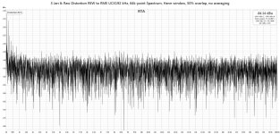
The system itself will have a spectrum floor that is the result of the converter, cables, and any (very minor) computer additions. The first Jpeg below shows the system itself at idle. Note that there is some more aggressive noise at 20Hz (-112dB) and 40Hz (-116dB) but outside of these lower frequencies, all is at -135dB or below. This is plenty quiet enough for this kind of testing.
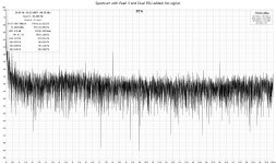
Now, let's add the Pearl 3 plus dual PSU into the chain and look first at just the spectrum noise floor. And the news is great here. The problem lower FR is amplified, markedly so for 20Hz. But look over the broad FR – most of the time the same -135dB noise floor is maintained.
Now if you look closer at the individual spikes you will see that harmonic multiples at 8k and 16k are strong and lesser spikes at 4k and 6k are also higher than normal. This is a theme that we will see amplified in the test tones coming up.
Would like to stress at this time that the overall noise of the Pearl 3 with dual PSUs and pre-regulation is tremendously low as measured above. This is what I have been reporting through aural tests and these figures are better than I had expected (way, way better).
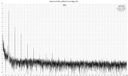
Now to see some operation data. Ran a 1Khz test tone through the P3 at 200mV – a good range for my MC cartridge listening level. The results are shown in the Pearl 3 at 1KHz JPeg below.
Overall, the P3 remains one quiet puppy. But there is a lot of harmonic ringing. The 2nd, 3rd, 4th and fifth overtones are strong – surprisingly so. From my listening experience I would not have expected this. Remember that this is an amplification of the spikes seen above when looking at the idle state. ALSO, and this is important, a portion of these spikes are the result of the SG. Tried the same 1KHz test tone with both the Rigol and the REW SG alone and they both showed harmonic ringing of their own – with the P3 out of the chain. Subtract this from the Pearl 3 output and the harmonics are reduced.
SO...
The kind gurus on this site might wish to discuss the test tone results. And it is always good to remember that the testing method is described exactly and I make no claims for the results except they are what the testing tools show -- that and the fact that the super low noise is confirmed by my ears. Got a better system? Let's hear your results! But the good folks on this thread are too civilized to allow cheap shots...
First, the measuring system. Am using a core of RME UCX A/D/D/A converter connected by USB to a HP computer running REW. The measurements shown here are from the RTA section of REW that is precise and straightforward. For test tones am using a Rigol DG1022 – a signal generator I have come to trust.
Measuring components has many pitfalls and a basic concern is how much system noise/distortion is there before the testing component enters the chain.
The system itself will have a spectrum floor that is the result of the converter, cables, and any (very minor) computer additions. The first Jpeg below shows the system itself at idle. Note that there is some more aggressive noise at 20Hz (-112dB) and 40Hz (-116dB) but outside of these lower frequencies, all is at -135dB or below. This is plenty quiet enough for this kind of testing.
Now, let's add the Pearl 3 plus dual PSU into the chain and look first at just the spectrum noise floor. And the news is great here. The problem lower FR is amplified, markedly so for 20Hz. But look over the broad FR – most of the time the same -135dB noise floor is maintained.
Now if you look closer at the individual spikes you will see that harmonic multiples at 8k and 16k are strong and lesser spikes at 4k and 6k are also higher than normal. This is a theme that we will see amplified in the test tones coming up.
Would like to stress at this time that the overall noise of the Pearl 3 with dual PSUs and pre-regulation is tremendously low as measured above. This is what I have been reporting through aural tests and these figures are better than I had expected (way, way better).
Now to see some operation data. Ran a 1Khz test tone through the P3 at 200mV – a good range for my MC cartridge listening level. The results are shown in the Pearl 3 at 1KHz JPeg below.
Overall, the P3 remains one quiet puppy. But there is a lot of harmonic ringing. The 2nd, 3rd, 4th and fifth overtones are strong – surprisingly so. From my listening experience I would not have expected this. Remember that this is an amplification of the spikes seen above when looking at the idle state. ALSO, and this is important, a portion of these spikes are the result of the SG. Tried the same 1KHz test tone with both the Rigol and the REW SG alone and they both showed harmonic ringing of their own – with the P3 out of the chain. Subtract this from the Pearl 3 output and the harmonics are reduced.
SO...
The kind gurus on this site might wish to discuss the test tone results. And it is always good to remember that the testing method is described exactly and I make no claims for the results except they are what the testing tools show -- that and the fact that the super low noise is confirmed by my ears. Got a better system? Let's hear your results! But the good folks on this thread are too civilized to allow cheap shots...
Attachments
Are you using a test fixture between your generator and the Pearl 3? If you are not, then you are running close to the lower limit of your DAC and measuring quantization distortion. Or maybe the Pearl is clipping?
There are examples of test fixtures earlier in the thread (Mark?). Me, I used a first 47K5 in series with two 26R7 in parallel in series with another 47K5. (These values are what I had on hand in low noise RN65 format). I connected the generator to the two ends of the network, and the Pearl on the two middle nodes, so having the pair of 26R76 in shunt across its input simulating MC cartridge coils. This is a divide by 7142 network, or 77.1 dB. This way the generator can meet its spec while the Pearl receives a tiny signal with the jumper off (high gain). The distortion was so low as to be hard to measure. I had to use 1 million points FFT and measured 0.0002 %, mostly second harmonic. Hope this helps!
There are examples of test fixtures earlier in the thread (Mark?). Me, I used a first 47K5 in series with two 26R7 in parallel in series with another 47K5. (These values are what I had on hand in low noise RN65 format). I connected the generator to the two ends of the network, and the Pearl on the two middle nodes, so having the pair of 26R76 in shunt across its input simulating MC cartridge coils. This is a divide by 7142 network, or 77.1 dB. This way the generator can meet its spec while the Pearl receives a tiny signal with the jumper off (high gain). The distortion was so low as to be hard to measure. I had to use 1 million points FFT and measured 0.0002 %, mostly second harmonic. Hope this helps!
No clipping and no low dac levels. All equipment is operating within range and there is no quantization distortion. If you perceive the data to be incorrect speak to specifics.
Ran a 1Khz test tone through the P3 at 200mV – a good range for my MC cartridge listening level.
MC cartridges output less than a millivolt. Without a voltage divider as described above there is the risk to saturate the P3.
- Home
- Amplifiers
- Pass Labs
- Pearl 3 Burning Amp 2023