This would, indeed, simplify things considerably!!! Is this really something that I can do and expect 0 side effects? Perhaps the internal filtering of the module assumes correct L/N connections and I would be introducing potential problems? Or is this just normal practice?...If you swap the PCB tracks to AC/L and AC/N of the IRM-03-12 the board will be better. Mains voltages are not polarized AFAIK and now the PCB tracks/traces are crossing each other 🙂
Thanks,
Rafa.
Rafa,
again:
- 7mm between earth (PE) and L
- 7mm between earth (PE) and N
- 3mm between L and N
JP
again:
- 7mm between earth (PE) and L
- 7mm between earth (PE) and N
- 3mm between L and N
JP
Once your PCB enclosed, do you know when plugging exactly that the L line is going to the L line of the AC/DC converter?
JP
JP
This would, indeed, simplify things considerably!!! Is this really something that I can do and expect 0 side effects? Perhaps the internal filtering of the module assumes correct L/N connections and I would be introducing potential problems? Or is this just normal practice?
Thanks,
Rafa.
The SMPS module does not care about L and N connected to N and L. That comes with AC and the almost worldwide "non polarized" connectors for mains voltage 😀 Don't do this with inputs/outputs and DC...
If you can turn a mains connector like Schuko 180 degrees and it can be plugged in then no one knows for sure if L is connected to L and N to N. Now, if these things are unknown to you please consider to gain knowledge first and then work with mains connected stuff. Normally one starts with a battery, a switch, a resistor and a LED. Mains voltage can bite.
Last edited:
We have been discussing this for 6 pages! And it is the first time I understand that clearly. Thanks for the line-per-line breakout, that makes more sense now. Great.Rafa,
again:
- 7mm between earth (PE) and L
- 7mm between earth (PE) and N
- 3mm between L and N
JP
Well, we use NEMA 5-15 grounded type B plugs here. There is no way you can turn that 180°, and unless your house wiring was done incorrectly, L is L and N is N, never the other way around....If you can turn a mains connector like Schuko 180 degrees and it can be plugged in then no one knows for sure if L is connected to L and N to N. Now, if these things are unknown to you...
So, as much as I request and appreciate the help, I would also appreciate a bit of a less patronizing tone. Precisely, because I am trying to adhere to more demanding EU and other international standards that I am not familiar with nor have anything to do with our local regulations is that I am insisting on understanding. So, I really appreciate learning that people design not knowing which will be L and N. It's very useful information. Thanks.
Rafa.
Less patronizing? Basic knowledge of AC is necessary to do mains related stuff. I think you have got friendly and to the point help. Please check the first post and what the level was then. It would be OK to make stuff as safe as possible regardless of local or international regulations. Just choose the most strict norms and you'll be OK. It is not a question of where you live but how you and your family members survive your DIY stuff when something goes wrong.
Even if ones home gets its 230V through a pole mounted spiders web of locally approved purple 1 mm2 cabling then adhering to safest-as-possible methods will make sure it was not your fault or your DIY device when things go south.
Even if ones home gets its 230V through a pole mounted spiders web of locally approved purple 1 mm2 cabling then adhering to safest-as-possible methods will make sure it was not your fault or your DIY device when things go south.
Last edited:
Yes, that is the part that is really helpful. I think that if I push the front connectors a tad to backwards I can connect the IRM module correctly, if I revert the N and L it's much cleaner! Thanks. I am trying to learn and I honestly appreciate all the comments.
The bottom part looks like this now (I am slowly working into adding all parts instead of two boards, not there yet).
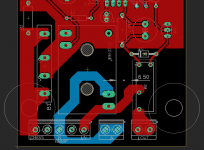
I did replace the Relay with JPs suggested part, I always thought that 16A or even 12A was overkill here, for those requirements, I'd probably go with H9KPXG. So 5A is more than enough.
I do still want to keep the 10mm separation, so, since I cannot seem to fit this in 50mm, I have a bit more front realstate, so I believe I now observe the full 7mm without the need of the "ditches" in the PCB to the chass line. I did use top and bottom layers to separate L from N, but 3mm are observed everywhere as well between L and N.
I like the idea of making the left mounting hole actually chassis connected. One could always Isolate that bolt if you want it not to be.
If I follow Jean-Paul's suggestion and invert L and N on the IRM module, then I can even move the connectors all the way to the front and do without that blue trace "in front" of the connectors, which I like a lot better.
What do you think?
Now on to work on the 'top' part of the PCB, I'm incorporating all the logic into the board as well.
Thanks once more,
Rafa.
That is continuous current. The relay will switch on/off what kind of load? Resistive, inductive or the worst ... capacitive...
Some devices/loads present a way larger inrush current. Some devices like some electrical motors even 12 x I nominal. It is a good habit to dimension relay contacts to the possible load and then over dimension them a tad. Just some info. It helps to limit currents to the maximum admissible current when the mains current is limited to a relatively high 16A. The aforementioned fuse is a good means.
The design looks much better like that.
Last edited:
...we use NEMA 5-15 grounded type B plugs here. There is no way you can turn that 180°, and unless your house wiring was done incorrectly, L is L and N is N, never the other way around.....
I am sorry if this sounds patronizing.
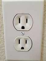
In the US, 5% to 60% of 3-pin outlets are wired L/N reversed. It is so VERY common that we have a standard "3 light" tester. And that is sometimes the only tool an electrical inspector brings.
My UK friends swear this never happens in the UK, and maybe your electricians in Ecuador always get it right. But bet-your-life reliable polarization is rare in the world.
Also any e-musician can turn-over a NEMA 5-15 plug. Bust-off the ground pin. Now the two flat blades are EQUAL width, not polarized-width like a US 2-blade plug.
And we have not got to broken Neutral (up to 115V can appear on the White wire through other loads).
J-P probably has good insight since his area's Schuko plug is reversible, historically has many variations which may or may not have 'ground', and is common worldwide.
Attachments
Last edited:
I can bet my salary this is as far from the truth as possible. I usually do try to measure (with a self testing UPS) that, at least, ground is working on my home plugs, but there are times that the third earth pin is left not connected to anything! It doesn't do anything, right? 😱...and maybe your electricians in Ecuador always get it right...
So yeah, point well taken. I wish to correct my statement: a "correctly" built NEMA could not be 180° turned. But yeah, I concede, you cannot ensure a line or neutral.
Jean Paul is right, not even the plugs can ensure that.
Rafa.
The SMPS module does not care about L and N connected to N and L.
Depends on what's connected between N and the secondary. Some have a 1 nF, several kV capacitor between N and V- on the secondary side.
I'd check with Mean Well before just swapping the connections. Their customer service is usually quick to respond.
That said, you can easily swap back to L->L; N->N by routing north from the N output connector.
Precisely, because I am trying to adhere to more demanding EU and other international standards that I am not familiar with nor have anything to do with our local regulations is that I am insisting on understanding.
You're already far ahead of the typical DIYer in that you are considering electrical safety. Good for you!
Tom
In the US, 5% to 60% of 3-pin outlets are wired L/N reversed.
I find that really hard to believe. I have one of those outlet testers and have tested the outlets at the places I've lived in (both in the US and in Canada). While I was house hunting in the US I also tested the outlets in the houses I viewed (or at least the ones I considered buying). I didn't find a single mis-wired outlet. I did learn that some circuit breakers have GFCI built-in by accidentally pressing the GFCI test button. 😱
Also any e-musician can turn-over a NEMA 5-15 plug. Bust-off the ground pin. Now the two flat blades are EQUAL width, not polarized-width like a US 2-blade plug.
Yeah. You can't prevent someone from tampering with the cord. There's no such thing as "fool-proof" or "child-proof". 🙂
Tom
Thanks for the insight Tom! Yeah, I think at this point, the polarity of the IRM module adds only about 3mm to the board if I don't switch. So I will research a bit, and then just go with one or the other.
Here is the full board and schematic with the reversed L/N on the IRM:

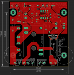
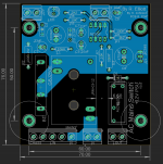
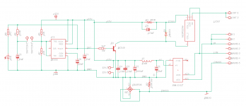
What do you guys think? Any crucial (or minor?) errors still present?
I added a 12V out terminal, it was always part of the intention to get a 12V PSU out of this. In the previous iteration, that was accomplished by the "breakout" connector that accepted the control out back. In this case, since that is already built into the system, I have now added an extra terminal.
Of note:
One additional question: on JPs PCB, he has doubled the traces for L/N/Chass on both top and bottom layers (as I have done with the ground plane). Is this a wanted addition to double on the layers in order to have more copper area for the lines? Or is it "safer" to have them like this version 0.5 I am presenting here with them "alternating" one on the top layer and one in the bottom?
They do adhere to the 7mm / 3mm spacing discussed previously, so they could also be a single layer solution for the L/N/Ch traces.
Thanks once more! Best regards,
Rafa.
Here is the full board and schematic with the reversed L/N on the IRM:


What do you guys think? Any crucial (or minor?) errors still present?
I added a 12V out terminal, it was always part of the intention to get a 12V PSU out of this. In the previous iteration, that was accomplished by the "breakout" connector that accepted the control out back. In this case, since that is already built into the system, I have now added an extra terminal.
Of note:
- Now that all is on a single board, I removed the extra 10K resistor suggested in post #2 by Rayma. I hope that was the right move?
- I added a extra 0.1uF capacitor next to the 12V output, mimicking Mark's 3x0.1uF placed on different places. I did comment on the original post that my initial research pointed that these were spread out to prevent oscillations, but no one either validate or contradicted this assumption / research. Perhaps this addition is a good place to ask again?
- The new relay has a 720Ohm coil, so I have upped the resistor value of R3 to 680 on the schematic, the PCB still shows the old value, but that is just a marking.
One additional question: on JPs PCB, he has doubled the traces for L/N/Chass on both top and bottom layers (as I have done with the ground plane). Is this a wanted addition to double on the layers in order to have more copper area for the lines? Or is it "safer" to have them like this version 0.5 I am presenting here with them "alternating" one on the top layer and one in the bottom?
They do adhere to the 7mm / 3mm spacing discussed previously, so they could also be a single layer solution for the L/N/Ch traces.
Thanks once more! Best regards,
Rafa.
.... there are times that the third earth pin is left not connected to anything! It doesn't do anything, right? 😱 ....
Yes, that house where 60% of the 3-pin kitchen outlets were H/N swapped, "didn't matter" because ALL those annoying green wires were cut off. (Also two 20A breakers fed one 15A circuit, to pretend to be 1972-compliant.)
Lets not talk about unenclosed splices in hidden space.
Obviously Tom shops better neighborhoods than I do.
Rafa, the board looks good. The 12V connector is at a "corner" which is unusual. Also uneccessary as the connector for the switch can be moved to the right a little, just like C5, R8, R5. You could consider to use SMD resistors 0805. Gut feeling says to use a somewhat more sturdy transistor to drive the relay like BC337. As the LED will serve as a power LED it serves little purpose on the board as mains voltage boards are usually at the back of a device. A molex KK connector (2.54 mm pitch) for a 2 wire cable assembly with a front panel LED seems more appropriate. Or, if it only serves to show correct functioning then an SMD LED could be used. Or both, in series!
The connector for the switch could also be a Molex 2.54 mm KK connector. Since no current is switched there will not be any thick wiring necessary. For some reason I think it is pleasant to use Molex KK for low voltage purposes and Phoenix MKDSN for mains voltage purposes. One can not make a mistake then.
I am sure the guys at Mean Well will have a laugh when you ask if L and N can be reversed.
Last edited:
Thanks once more.
I think the KK connectors make for a nice improvement. For this particular design, I am going to avoid SMDs. Regarding the transistor, is BC337 a direct replacement in this circuit? Or do I need to recalculate the 2K2 resistor and potentially other places to have it working correctly?
Since that part I am following the P166 to the letter, I haven't yet studied such alternatives.
With that pending, here is the board with some of the suggestions you made:
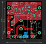
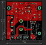
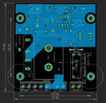
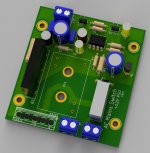
I ended up using 0.8mm traces everywhere on the "top" part of the circuit (not the mains and chassis, we have discussed that already, those are fine 😛 ). Is it better? Should I revert to 0.4mm? It doesn't matter?
Thanks for any feedback, best regards,
Rafa.
ps: the large IRM PSU brick is omitted from the rendering as to be able to see something! 😛 And I haven't yet found the nice 5x euroblock connector model, so it's a boring block there in the bottom. 🙂
I think the KK connectors make for a nice improvement. For this particular design, I am going to avoid SMDs. Regarding the transistor, is BC337 a direct replacement in this circuit? Or do I need to recalculate the 2K2 resistor and potentially other places to have it working correctly?
Since that part I am following the P166 to the letter, I haven't yet studied such alternatives.
With that pending, here is the board with some of the suggestions you made:


I ended up using 0.8mm traces everywhere on the "top" part of the circuit (not the mains and chassis, we have discussed that already, those are fine 😛 ). Is it better? Should I revert to 0.4mm? It doesn't matter?
Thanks for any feedback, best regards,
Rafa.
ps: the large IRM PSU brick is omitted from the rendering as to be able to see something! 😛 And I haven't yet found the nice 5x euroblock connector model, so it's a boring block there in the bottom. 🙂
ALL those annoying green wires were cut off.
Yeah... Then connect Neutral to the ground terminal to fool those 3-prong electrical testers. My former boss raved about that one as the greatest trick in the book. It's probably good he was mostly a digital designer. 🙂
Lets not talk about unenclosed splices in hidden space.
Heh. My house is from 1913, so I've seen my fair share of weird stuff as well. It's all part of the experience. At least the electrical was upgraded to modern code before I moved in.
Tom
Thanks JPS64, yes, good resource for blocks. I have added that one.
You had also the bridge to a much higher degree of mesh resolution than my "box" and also nice caps that have the Xs on top, and all that jazz, but it's OK, for me, the objective is to know if things mostly look good, not producing the perfect result (although the former architect / animator / 3d renderer in me still misses that level of realism 🙂 ).
Thanks once more more the resources.
Last edited:
- Home
- Amplifiers
- Power Supplies
- PCB: Push on / Push off Mains Switch
