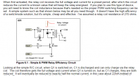
You can just choose the -40 version as there is no such thing as too high hFE here.
True. Though don't read too much into the data sheet. hFE tends to drop as the transistor approaches saturation. Also, the 2.2 kΩ base resistor will allow for quite a bit of base current.
Tom
One could avoid the saturation/hFE issue by using an NMOS like the 2N7000. Just saying. I'm normally not a MOS guy but they do make great switches.
And the 2N7000 is an NMOS. I checked. 😉
Tom
And the 2N7000 is an NMOS. I checked. 😉
Tom
Relay driver (and optoisolator driver for the "soft start" function you are not implementing) are both MOSFETs on the board linked below. It might give confidence that such things are possible to get right.
Nchannel MOSFET (datasheet) here.
PCB: low voltage On-Off switch drives AC mains relay \ includes soft start .. H9KPXG
_
Nchannel MOSFET (datasheet) here.
PCB: low voltage On-Off switch drives AC mains relay \ includes soft start .. H9KPXG
_
Last edited:
I haven't experienced this with good quality sealed relays like those produced by Schrack
Sadly TE/Schrack is not immune. I've recently had to resolve some issues that involved their relays.
See attached document from TE regarding the Care & Feeding of Relays.
Tom
Attachments
Dear friends, here is the list of parts I have compiled from all that we have talked in the last pages.
I'm attaching a .zip file with an .xlsx file inside. But I am also attaching a link to the Mouser project to hopefully save you time from copy pasting and instead allowing you to focus on commenting on what you think are not ideal parts for the project. I am very grateful for this.
Most part are straightforward, but the capacitors are always a tricky bunch, so I'd appreciate another set of eyes.
Mouser Project:
Mouser Electronics
I'm also including here a summarized local version in case you just want to have a quick look without getting into specifics:
Of note:
That's about it for the BOM. I have gone over the PCB once more and adjusted some spacings according to the selected parts (most notably, the smaller electrolytic capacitors went from 2.54 mm spacing to 2 mm spacing.
Also, I have tidied up the part numbers, so I'm attaching the schematic and PCB layout so there is no confusion.
Resources:


Thanks once more for all the help!
Rafa.
I'm attaching a .zip file with an .xlsx file inside. But I am also attaching a link to the Mouser project to hopefully save you time from copy pasting and instead allowing you to focus on commenting on what you think are not ideal parts for the project. I am very grateful for this.
Most part are straightforward, but the capacitors are always a tricky bunch, so I'd appreciate another set of eyes.
Mouser Project:
Mouser Electronics
I'm also including here a summarized local version in case you just want to have a quick look without getting into specifics:
Code:
B1		1	GBJ2506		833-GBJ2506-BP
C1		1	33uF		647-UKL1E330MEDANA
C2		1	1000uF		647-UHE1E102MPD		Usign 25V instead of Mark's 16V, higher ripple current, twice as much leakage current
C3, C4		2	0.1uF		871-B32529C1104M000
C5, C6		2	10uF		647-UMV1E100MFD1TP
C7		1	47uF		647-UTT1E470MDD1TD
C8		1	470uF		647-UPA1E471MPD6
D1		1	1N4004		621-1N4004
IC1		1	NE555		595-NE555P
K2		1	PCJ-112D3M,303	655-PCJ-112D3M,303
L1		1	10uH		871-B78108E1103K000	Drill size is 1mm, Lead Diam is 0.8, problem?
P1, P3, P5	3	Termblok-2	651-1935161
P2, P6		2	Header 2 pin	538-22-28-4023
P4		1	Termblok-5	651-1935190
PS1		1	IRM-03-12	709-IRM03-12
Q1		1	BC337		512-BC33725TAR		Original design called for BC549 (P/N 512-BC549BTA)
R1, R7		2	2.2K		594-MBB02070C2201FCT	Actual power rating 600mW
R2		1	100R		279-RR02J100RTB
R3		1	680R		603-MFR-25FTF52-680R	Lower coil resistance will require lower ohm Rs, which use more space.
R4, R6		2	10K		603-MF0207FTE52-10K	Actual power rating 600mW
R5		1	100K		594-MBB02070C1003FC1	Actual power rating 600mW
Of note:
- Most resistors of 0.25W were bigger and MUCH more expensive than the 0.6W versions posted. Not sure what is going on here and why that would be the case. Both versions where 1% tolerance. What am I missing?
- Since I have never built a PCB, instead of listing the very-useful PCB lead size that Mark lists on his spreadsheets, I have included the actual drill size listed on the Gerber files. As I understand it, those will get narrowed down once the copper layer is applied to the edge of the PCB
- Given the above, most drill holes fall into the expected range, except the 10uH inductor, for which the drill size is barely 0.2mm larger than the lead of the component. Should I increase that? Would it be a tight fit? Will it not fit at all? I'm planning on using 1oz copper, if that makes a difference
That's about it for the BOM. I have gone over the PCB once more and adjusted some spacings according to the selected parts (most notably, the smaller electrolytic capacitors went from 2.54 mm spacing to 2 mm spacing.
Also, I have tidied up the part numbers, so I'm attaching the schematic and PCB layout so there is no confusion.
Resources:
Thanks once more for all the help!
Rafa.
Attachments
Last edited:
I have all the confidence you can get them right. For an expert like you, all these parts are tools, just like oil paints or nature's pigments are tools for true artists. For me, they are a bit more like paint-by-numbers sets at this point, but I am going to try to devote some time to learn. I still need to work on my "real" job as to afford this hobby, so let's see how much time I can devote to this.Relay driver (and optoisolator driver for the "soft start" function you are not implementing) are both MOSFETs on the board linked below. It might give confidence that such things are possible to get right...
I have bought your famed $13 part tester, and a whole lot of inexpensive caps and resistors, arriving in a few days. I'll include a bunch of standard chips and transistors and learn by studying simpler circuits where the complexities are taken away and only the main issue at hand is kept, so that I can focus on learning. Most of what these do in circuits I am used to doing by software with rPis and Arduinos, so I need to learn the "analog" world.
I must confess that I also blew up more than my usual hobby budget and have an oscilloscope coming in next week, hopefully to help in the learning and future circuit design and debugging.
If not, I just bought a nice looking TV-like gadget that will show some strange shows of colored lines 🙂
Let's see, thanks a lot!
Rafa.
Hi, I think you have designed/composed a nice and good working device and a good PCB. Just build it and report back how it works and if you are satisfied.
Don't let the well meant interference and noise (to use some familiar terms) created by us influence your self confidence. It is vast framework of small rules and interconnected things that one will master when learning stuff step by step with an open mind and care for details.
Most of us started with copying stuff designed by others as the knowledge was not there yet. Normally that phase ends one day. As long as you don't sell boards commercially there is nothing wrong with copying/composing. Therefor the names of the people other than yourself on the PCB serve no purpose IMHO as the list should be longer with Edison, Tesla, Bell, Volta, Mr. Ampere etc. When you buy bread the bread does not have the name of the farmer that grew the corn and/or the guy that made the recipe for the dough on it does it?
Last edited:
Well, it's been almost a month, but the PCBs from DigiKey have finally arrived, along with all the components from Mouser!
The PCB went really well, I think, the parts purchase as well. Long journey to Ecuador, that's for sure. 🙂
Here's the PCB:

And here it is with all the parts populated:

If 16v caps are enough, the very tall 1000uF capacitor can be switched with a much smaller one that will fit with the overall proportions of the PCB, but this 25v is good enough, I guess.
Also, I did some measurements on two key areas: the coil and the actual 12V psu.
Coil Voltage
The voltage in the coil is a very clever solution as implemented by Mark, in my opinion. The coil, when on, does not see the full 12V, but, depending on R3, a nice fraction of it. If matched with the coil, half the voltage (I failed to see this before, it is quite obvious now), so it will nicely extend the life of the relay.
Here are then voltages across the coil upon start and stop:


As you can see, the relay is triggered quickly, and then slowly settles to half the voltage during ON status. When Q1 stops conducting, it is a clean cut back to 0V. Really nice. The blue trace is the voltage on the LED+ pin, and the red is just my trigger on the SWITCH leg.
PSU
The PSU implementation is also really nice. I measured as best I could the ripple of the PSU alone and then after the implementation of the filtering system. Please note that I don't have the knowledge nor the equipment to do 'accurate' PSU measurements, these should be taken simply as 'referential' value to see the improvement, rather than claims that PSU ripple is X or Z.
I measured around 30mV of peak-to-peak ripple / noise onto a 120 Ohm load (100mA current) of the SPU without any filtering applied:

After implementing the filtering with the inductor and the caps, I measured 240uV (which is below my test implementation's limits probably):

Again, that is not to say that ripple is 240uV, or that the original ripple is actually 30mV, that was already better than the manufacturer's specs! So, this is just a 'before and after' type of comparison for me to learn and to show that the filtering is actually having a positive effect in the system, not to claim such specs of the design / implementation.
So, this looks rather reasonable to me, I'm quite happy. I'll look into implementing it on my 24V external PSU for the ACP+ and see how that turns out.
I'm attaching the Gerber files as sent to DigiKey, which produced the pictured PCB. Since this is my first time with Gerber files, I suggest that, should you want to manufacture this PCBs, you inspect the files in one of the free viewers so that you confirm they are working for your specific needs.
I'd like to thank everyone for their input, suggestions and critique! As you can see, I have labelled this v0.6, so I consider this still in "beta" status, should people have more input and suggestions that could improve upon the design.
My biggest thanks,
Rafa.
The PCB went really well, I think, the parts purchase as well. Long journey to Ecuador, that's for sure. 🙂
Here's the PCB:
And here it is with all the parts populated:
If 16v caps are enough, the very tall 1000uF capacitor can be switched with a much smaller one that will fit with the overall proportions of the PCB, but this 25v is good enough, I guess.
Also, I did some measurements on two key areas: the coil and the actual 12V psu.
Coil Voltage
The voltage in the coil is a very clever solution as implemented by Mark, in my opinion. The coil, when on, does not see the full 12V, but, depending on R3, a nice fraction of it. If matched with the coil, half the voltage (I failed to see this before, it is quite obvious now), so it will nicely extend the life of the relay.
Here are then voltages across the coil upon start and stop:
As you can see, the relay is triggered quickly, and then slowly settles to half the voltage during ON status. When Q1 stops conducting, it is a clean cut back to 0V. Really nice. The blue trace is the voltage on the LED+ pin, and the red is just my trigger on the SWITCH leg.
PSU
The PSU implementation is also really nice. I measured as best I could the ripple of the PSU alone and then after the implementation of the filtering system. Please note that I don't have the knowledge nor the equipment to do 'accurate' PSU measurements, these should be taken simply as 'referential' value to see the improvement, rather than claims that PSU ripple is X or Z.
I measured around 30mV of peak-to-peak ripple / noise onto a 120 Ohm load (100mA current) of the SPU without any filtering applied:
After implementing the filtering with the inductor and the caps, I measured 240uV (which is below my test implementation's limits probably):
Again, that is not to say that ripple is 240uV, or that the original ripple is actually 30mV, that was already better than the manufacturer's specs! So, this is just a 'before and after' type of comparison for me to learn and to show that the filtering is actually having a positive effect in the system, not to claim such specs of the design / implementation.
So, this looks rather reasonable to me, I'm quite happy. I'll look into implementing it on my 24V external PSU for the ACP+ and see how that turns out.
I'm attaching the Gerber files as sent to DigiKey, which produced the pictured PCB. Since this is my first time with Gerber files, I suggest that, should you want to manufacture this PCBs, you inspect the files in one of the free viewers so that you confirm they are working for your specific needs.
I'd like to thank everyone for their input, suggestions and critique! As you can see, I have labelled this v0.6, so I consider this still in "beta" status, should people have more input and suggestions that could improve upon the design.
My biggest thanks,
Rafa.
Attachments
Last edited:
I have edited the first post with Links to the most recent posts that have 'useful' files. I'll keep updating that if and when new versions come along.
That looks very good! Good change management too.
Now about the clever solution to reduce coil power.... I don't think it will extend relay life as that is mainly destined by the times the relay switches. How often does one see a defective relay coil? My opinion is that it will result in the opposite and I will defend it:
I would call it clever when switching voltage as in input switching of for instance amplifiers but I would never use it for current switching and definitely not for mains switching with "normal" relays (I deliberately avoid latching relays here). I may be wrong (I am pretty sure I am not) in this but using half the voltage results in less contact pressure. The manufacturer does not mention the relay having a 12V coil without a reason. It IS a 12V relay specified for 12V, for 6V a 6V version would have been needed. I would use a wire jumper here for the resistor and omit the cap. Please note that even with exact 12V the relay already will have lower voltage because of the transistor. While you can lower the voltage after the relay has switched half the voltage may result in contact pitting certainly when the relay is in the region of minimum holding current.
So it seems the clever trick is useful in voltage switching but less clever in current switching. A more clever trick is to choose a relay version with higher coil resistance that is still rated for the current one wants to switch OR to switch 🙂 to latching relays at the expense of a higher price and added complexity.
Last edited:
Well, since I don’t know a thing about relay coils, every change introduced to the original design is, more or less, easily removed or bypassed.
If that is a concern, installing a jumper instead of R3 will remove the voltage divider and bypass cap and just present the full 12V to the coil.
Interesting remark Jean Paul, I’ll research a bit if this has impact. Thanks!
If that is a concern, installing a jumper instead of R3 will remove the voltage divider and bypass cap and just present the full 12V to the coil.
Interesting remark Jean Paul, I’ll research a bit if this has impact. Thanks!
Here's a good read on the subject by the manufacturers of the Relay I bought:
https://www.te.com/usa-en/products/...elay-contactor-performance.html?tab=pgp-story
Of note:
https://www.te.com/usa-en/products/...elay-contactor-performance.html?tab=pgp-story
Of note:
Coil power Reduction Schemes (DC Coil Relays Only)
It is sometimes desirable to reduce total control power consumption and reduce heating. One way to do this is to use relays with latching mechanisms, however they are relatively expensive and may leave the relay in an undetermined state in the event of a power failure. An alternative is to reduce the coil power consumption on standard DC coil relays using one of the following techniques.
- PWM (Pulse Width Modulation) - With this scheme, the DC coil relay or contactor is initially operated at nominal coil voltage, or slightly above, for a short interval to operate and stabilize the relay mechanism. The relay coil is then driven by a rectangular wave pulse train of some specified amplitude, duty-cycle and frequency to hold the relay in the operated condition with less power applied.
- Step-Down DC Coil Drive - Like PWM, this technique initially operates the relay at nominal rated DC coil voltage for a short interval to operate and stabilize the mechanism. Then the DC voltage is reduced to a lower level to hold the relay in the operated condition with less power applied.
- Caution - Use of “charge-pump” and similar other schemes can accomplish the same purpose, but they use charging/discharging capacitors for power. The resulting non-rectangular wave-shape makes it very difficult to ensure that stable, proper coil power is applied to the relay coil for the proper time interval to properly operate the relay or to hold it properly engaged while reducing coil power. Though commonly used, such schemes are not recommended due to the difficulty in ensuring proper coil drive.
Similarly, one must always remember that reduction of coil power reduces the holding power of the relay’s coil and thus reduces shock and vibration tolerance in the application.
TE Relay Products Engineering should be consulted for relay family specific information for all of these techniques. Not all relays perform the same.
Yes I was careful but I was pretty sure that the "clever" should be substituted for another word 😀 Oh oh the tone...
Now if you have used the type ALDP112 then at 12V the coil is 720 Ohms and current is 16.7 mA. Not so long ago LEDs needed that current to glow 🙂 The power is 200 mW nominal. What is there to gain with regards to power reduction? The device won't be switched on 24/7 I hope.
Premature conclusion: the relay will live shorter and possible failure.
Last edited by a moderator:
Please research possible failure of H9KPXG relay contacts at nominal load/rated current and if necessary notify builders for a modification. Sorry.
* as said, the idea is safe when switching voltage/signals (in general). The context can not be seen but I hold Rod Elliott in high esteem and the schematic is likely for input switching (assumption, please confirm) and he was not involved with H9KPXG so Rod is not to blame.
* as said, the idea is safe when switching voltage/signals (in general). The context can not be seen but I hold Rod Elliott in high esteem and the schematic is likely for input switching (assumption, please confirm) and he was not involved with H9KPXG so Rod is not to blame.
Last edited:
Note: for a complete view on this matter I asked Rod Elliott for a reaction. Since his website is the modern encyclopedia for audio DIYers it maybe handy to have this schematic explained more clear and the exact use of it.
Rod Elliott replied that the 'efficiency' circuit showed (his version) works perfectly if the components are selected properly. Also that it is not his invention and that it is used in countless products... Mmmm.
So this application is copied and again copied and now it turns up in a new design 🙂 Now there are manufacturers that describe methods to reduce coil power. All in context but this is then not about 200 mW relays and it is only about reducing power at the expense of higher sensitivity for shock/vibration and there is not a word spent regarding extended relay life. A relay coil specified for 12V is meant for 12V with a +/- margin as specified in the datasheet. One may gamble with voltage switching but why? Modern relays consume little power when compared to their older cousins. Their reputation is already tarnished and this circuit does not make it better for them.
I recommend strongly against the circuit when mains circuits and/or current switching is done but maybe it is better to forget the circuit completely as it may be copied by DIYers. So please let's stop the cycle and aim for reliable and safe circuits with relays.
Last edited by a moderator:

A relay has a couple characteristics that should be considered. First is the massive inductance, which limits the initial inrush current and produces a massive fly-back pulse when it's turned off. Hence a damper is not optional. An RC network is a possibility but inefficient and ineffective compared to a diode for DC or a MOV for AC relays.
Next is the holding vs turn on voltage. This is because the magnetic circuit closes when the relay is energized boosting the flux and holding force vs the initial unenergized state. A better holding circuit is an initial high voltage on a capacitor that takes seconds to charge and a diode to a lower holding voltage.
Relay power can be a real problem and many commercial devices resort to latching relays that require zero power to stay in the current state, but that then requires a pulse to turn them off.
https://www.te.com/commerce/DocumentDelivery/DDEController?Action=srchrtrv&DocNm=13C9133_DC_Relay_Power_Reduction_AppNote&DocType=CS&DocLang=EN
https://assets.omron.com/m/3e54678f7feeb2fc/original/LY-Electromechanical-Relay-Datasheet.pdf
If the PCB design includes a microcontroller, then the uC can easily provide all necessary pulses and timing to operate a latching relay. As member steveu points out, latching relays dissipate zero power when not switching.
Interestingly, there are commercial examples of push-on, push-off, mains switch boards which DO include a microcontroller, but DONT use latching relays. Launching the Google search shown below, will find one such board ($169 + shipping).
_
Interestingly, there are commercial examples of push-on, push-off, mains switch boards which DO include a microcontroller, but DONT use latching relays. Launching the Google search shown below, will find one such board ($169 + shipping).
_
Attachments

In this circuit "as it is" C8 should be removed and R3 replaced for a wire jumper to avoid any inconvenience and correct behavior of the relay.
Of course latching relays as I suggested are nice (but expensive) and microcontrollers are toys for the engineers (and they're "ifs") but do we need all that? No we just omit the "efficiency network" and don't worry about the 200 mW/0.2W we use a few hours a day certainly compared to the power hungry, inefficient class A devices some build without blinking an eye 🙂 The ALDP112 relay can switch 5A/277V AC. Now we keep a safe margin so let's say we switch 1A consuming devices so 230V x 1A = 230W. The 0.2W of the relay is simply not counting in the whole picture. There is simply no benefit to think of against the negative points the RC network brings, no more no less.
Latching relays can be switched reliably with simple circuits. If we would need latching relays AND an ARM CPU (over-engineering 101) for this then maybe a real sturdy mains switch is a better choice as these separate mains and devices 100% when switched off, almost never breaks down, doesn't need a switcher permanently powered on and adds no complexity. Please note the circuit is developed as momentary switches are cheaper but are they really when everything is added up?
Last edited:
- Home
- Amplifiers
- Power Supplies
- PCB: Push on / Push off Mains Switch