Im in too
I hope it is not too late, I can help with the quantity, I'll get 8 and 4 protection. I am very aware that it might not be optimal. And if the ground causes problem it is not the 1st time I use copper foil and so art fashion to make it what I want.
TO3 is the way to go, I am just not that sure how the heat sink bracket is going on. But I was think L shape to go on the back wall, all of them vertical.
I've got the spectrum, network and scope to deal with these so I guess I'll be fine. Only problem is to design a proper PSU, I am thinking to go for SMPS but that would be my first SMPS design for an audio amp board.
I use to design radar IF boards, ADC, DDS ... So I should get this
Hi tchiwam,
Maybe you did not follow all the way. The boards (main, protection) are now consolidate into 1 so the # has to be same, actually just specify M will be good. Please send me an email of the order as in Post 6 but of course no need for the P# now.
Maybe you did not follow all the way. The boards (main, protection) are now consolidate into 1 so the # has to be same, actually just specify M will be good. Please send me an email of the order as in Post 6 but of course no need for the P# now.
Thank you bigPanda, just drop the P from my email. Or should I resend another email ?
Yours,
Philippe
Yours,
Philippe
Hi tchiwam,
It is OK, I know what you are after. Don't have to send another mail.
All buyers,
If you have any renew of your order, please add 'renew' to the title 'pcb order for Goldmun clone' and let me file them easier. Tks
It is OK, I know what you are after. Don't have to send another mail.
All buyers,
If you have any renew of your order, please add 'renew' to the title 'pcb order for Goldmun clone' and let me file them easier. Tks
Guys, mind to do it the right way as in Post #6, please.
Nagys,
I haven't yet receive anything from Alex. I will send the performa by tomorrow night. Hopefully I can see the files soon because I still have to see if they can generate the gerbers. May be alex is having trouble with the gerber generation as I had encountered earlier.
Nagys,
I haven't yet receive anything from Alex. I will send the performa by tomorrow night. Hopefully I can see the files soon because I still have to see if they can generate the gerbers. May be alex is having trouble with the gerber generation as I had encountered earlier.
Guys, mind to do it the right way as in Post #6, please.
Hi BigPanda,
I have send an order for 1 pair of TO3 board to your (email.com) mailbox.
Cheers - sng001
sng001,
I have process your order. Are you in NZ or HK?
All buyers.
I have get files from Alex and everything are OK. But it seems that we are experiencing a bias problem (If you are following the main thread all the way thru, you should have noticed it in the main link). Guess what we can do is wait now.
BTW, I have tried to change Alex's work a bit. I have printed the components ID instead of the value on the pcb : R15 in stead of 100k. Wonder which would you guys prefer?
We are now definitely going for the TO-3 version. If any buyer is not in favor of this, please state. Like I said, if there are enough TO-P votes, we may still be in business.
sng001,
I have process your order. Are you in NZ or HK?
Hi Bigpanda,
I live in Sydney, Australia; please add postage to the invoice.
Cheers, sng001
bambadoo,
Your order being processed.
jtwrace,
takes 10-14 days for fab. and another fortnight to get to buyer max (but there could be surprises). So something like 4 weeks max. If we can conclude on the pcb design in Nov, we should be getting them before Christmas -- damned the high season for posting again. Hopefully they can have them ready before 15th.
sory out off topic, may i use 2SK176 2SJ56 ?
Yes, they should work... They are rated for 200 volts instead of 140 volts. Do you know of a source for them?
Bigpanda - The BIAS resistor is R23 in the schematic. Goldmund uses a fixed resistor because it sounds better. Since we are using TO3 MOSFETS, the BIAS resistor should be 330 ohms. If they were plastic, it would have to be lower. As it is now, it takes the guessing out of the equation. Of course a variable resistor can be soldered in and adjusted in order to have a specific temperature on the MOSFETS, then measured and a fixed resistor could be finally soldered in.
Bigpanda - The final pair of boards should be mirror image? Correct? Otherwise one channel's speaker output wires will always be longer than from the other's...
Last edited:
Hi Nagys,
As far as I can remember about adjusting the bias for my previous projects, I always measure the current flowing into the outputs not the temperature of the outputs. This is beyond my experience on this subject and it's better you have a more detail explanation of the procedure . Even if you had adjusted first with a pot, you might not be able to get a fixed resistor with the exact same reading on the pot.
There is only 1 pcb layout. I never thought about the question you have raised : the difference between the length of the path from board to speaker output terminal.
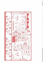
Here is what I had done with the value of the components. Haven't yet seriously check for error but will do it before Friday.
As far as I can remember about adjusting the bias for my previous projects, I always measure the current flowing into the outputs not the temperature of the outputs. This is beyond my experience on this subject and it's better you have a more detail explanation of the procedure . Even if you had adjusted first with a pot, you might not be able to get a fixed resistor with the exact same reading on the pot.
There is only 1 pcb layout. I never thought about the question you have raised : the difference between the length of the path from board to speaker output terminal.
Here is what I had done with the value of the components. Haven't yet seriously check for error but will do it before Friday.
Attachments
- Home
- Group Buys
- PCB order for Goldmun clone