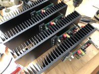

Looks very impressive. Can you give an indication of how big the heatsinks are ? I guess 300×100×40 mm ? On the back it says 60 watt. Did you use a 2x30 volt transformer for that ? I wish you success with your project. Jurjen
Last edited:
Itd 300*120*40. I use about 0.9 amps bias in total with dual 25v rails for a dissipation of 12w per fet. This gives a heatsink temp of about 40 degrees.

Yes…i have enough pcb’s. Send me the funds and i’ll send the pcb’s and doc by end of the week. Prices are unchanged
Dear Tarasque,
I received the new boards in good order. Thanks.
In the manual on the page with components I found 2 small errors ;
1. You sum up all resistors from number 1 to 52 including the values of them. After R27 you get R48 instead of R28. Value of R48 is 1K in te list, that's correct. Now we miss R28 on the list. That value is also 1K if I am correct.
2. On the new boards the Bias resistors are R18 and R17. On the former boards/schematic R17 was R43. On the new component list there is also a R43, but I can't find it on the board/schematic. So I think R43 is now R17 and can be erased from the list.
Greetings, Jurjen from Holland
Me again, sorry,
On top of the schematic you wrote ; for Exicon fets R17 + R18 = 240 ohm. IQ = 0,3 A/fet
Does this mean if we use Exicon fets each resistor is 240 ohm , or together 240 ohm ?
It's quite different than the values on the list; R17 is 1600 ohm and R18 is 80,6 ohm.
Please explain
Jurjen
On top of the schematic you wrote ; for Exicon fets R17 + R18 = 240 ohm. IQ = 0,3 A/fet
Does this mean if we use Exicon fets each resistor is 240 ohm , or together 240 ohm ?
It's quite different than the values on the list; R17 is 1600 ohm and R18 is 80,6 ohm.
Please explain
Jurjen
The resistor numbers: I have changed the resistor references so now the PCB references are matching the schematic references. R28 is no longer on the board.
The two bias resistors R17 and R18 are on both the versions of the PCB's. R18 is 80,6E and the other is defined by Hawk as 1k6. However that puts the amp in deep class A (~1,6A per fet) with the Exicon fets. The max dissipation of the fets that I'm confortable with is around 15W per fet. Given the fact that I'm using 35V supply's, the max bias I want to apply is ~0,4A per fet. For my fets that comes down to R17+R18 to be 240E
I've build a channel where I used a 1K pot instead of R17 and adjusted it to the value I intended to use when the amp is on normal working temperature. In my case this was 160E for R17
I am sorry, but R28 is on the board and schematic; it's connected to the base of Q8 on one side and to R23 on the other side. On the former schematic it used to be R24. On the new board it's next to C3.
- Home
- Group Buys
- PCB for the HAWK A18 amplifier (+ FETs if required)