To be clear. I have build a test channel and verified the corrected layout. It should be ok now.
The corrected boards are on order and ill build a channel and post the results
The corrected boards are on order and ill build a channel and post the results
The simple fact is that 2 (or 3) pairs of eyes see more. Also you seem to accept and correct errors on the fly which is not something builders are keen on. Builders desire an error free PCB without any need to turn parts or do guesswork.
Yes new pcb should be loaded and tested perfectly, then proper documentation (schematic, BOM, parts layout and specific instructions in English) to be supplied.
The current documentation is a mix of English and Dutch - which is not much use to the wider audience here. Also the state of the documentation is not clear with hand written notes and obviously missing all the corrections, changes and modifications you have done - which you have not listed clearly here in this thread. A GB is useless if you are going to supply faulty pcb's full of errors and then not clearly state all the corrections and changes.
Marcel, do you have an English version of the Hawk article you sent with the pcb's - being in Dutch does not help me one bit.
Last edited:
Hawk was a Dutch company serving the Dutch market mainly with excellent designs and the founder also was publisher of a Dutch audio magazine. Now any attempt to learn Dutch is a good attempt but it is not Marcels task to translate original documents I think. As a Dutch DIYer I deal with French, German, Polish, Chinese and Japanese texts and Google Translate helps a lot. Native single language speakers can not force others to translate everything published anywhere by others. The documents seem an extra service for background information and anyone can use Google Translate.
Having a 100% error free PCB with English BOM and schematic for international usage all checked by any capable third party however seems a normal thing to do. That there still will be a slight imperfection may happen and no one will have an issue with that. Group buys like these are a burden if it is a 1 man operation and cost a lot of time and energy with an error margin in every single step of the process. I noticed that error margins to be largely mitigated by the help of any person.
Having a 100% error free PCB with English BOM and schematic for international usage all checked by any capable third party however seems a normal thing to do. That there still will be a slight imperfection may happen and no one will have an issue with that. Group buys like these are a burden if it is a 1 man operation and cost a lot of time and energy with an error margin in every single step of the process. I noticed that error margins to be largely mitigated by the help of any person.
Last edited:
Your last sentence is all we need here, but somehow I think it is beyond the seller to provide a proper product. I have purchased the pcb and with so many errors and changes that have not been documented properly, it is an impossible task to get that board working as it stands now.
Sometimes more is offered than strictly needed 🙂 I discretely offered my help to smoothen out things and my Dutch and English both are not the worst I think. I have been in such Group Buys or PCB projects and it can be frustrating as the intention of course is to deliver an outstanding device.
Last edited:
I hope Marcel takes up your offer, as if you look back at the beginning of this thread you will see he got the first batch of boards wrong and now with this new batch, the problem is still there but far worse as to the amount of errors.
Post #33 will lead you there and those errors were found by a member who purchased the pcb's - not Marcel himself.
Post #33 will lead you there and those errors were found by a member who purchased the pcb's - not Marcel himself.
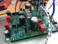
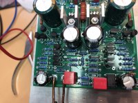
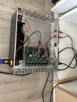
All…I have redesigned the pcb and corrected thr mistakes as well as the mistakes that were in the design from John (Hawk).
I build test channels and they are working as designed.
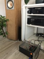
The amp is a big step up from my previously A18 implementation. More space, darker background and better definition.
The improvements implemented.
1. Corrected the orientation of some parts
2. Increased the space for some caps
3. Added the option to switch between class A and AB by meder relais.
4. Changed the hole diameter to snugfit the amp connectors and better fit for the FETS
5. Removed the connections for the Toshiba fets. These fets have a high Gm and i found it to work less well in an amplifier without feedback.
6. Now used 2mm FR4 boards instead of 1.6mm
7. Now used 2 oz copper instead of 1 oz
8. Corrected and recalculated the servo loop and added a required ground connection.
9. Changed the supply for the servo loop to accomodate higher supply rails.
10. Corrected the artwork to correctly connect the current source fets (J112)
See my new and fully build board:
I build test channels and they are working as designed.
The amp is a big step up from my previously A18 implementation. More space, darker background and better definition.
The improvements implemented.
1. Corrected the orientation of some parts
2. Increased the space for some caps
3. Added the option to switch between class A and AB by meder relais.
4. Changed the hole diameter to snugfit the amp connectors and better fit for the FETS
5. Removed the connections for the Toshiba fets. These fets have a high Gm and i found it to work less well in an amplifier without feedback.
6. Now used 2mm FR4 boards instead of 1.6mm
7. Now used 2 oz copper instead of 1 oz
8. Corrected and recalculated the servo loop and added a required ground connection.
9. Changed the supply for the servo loop to accomodate higher supply rails.
10. Corrected the artwork to correctly connect the current source fets (J112)
See my new and fully build board:
Attachments

Did simulations and found that the virtual impedance is similar with one or 2 resistors to ground.
Good to see the new pcb Marcel,
Now, will you be supplying correct new schematic, BOM and parts layout drawing with this new pcb?
What part numbers did you use for the Exicon fets?
What is the deal for those members who purchased the unusable first pcb with very poor documentation. I sent you a PM on this a week or so ago.
Now, will you be supplying correct new schematic, BOM and parts layout drawing with this new pcb?
What part numbers did you use for the Exicon fets?
What is the deal for those members who purchased the unusable first pcb with very poor documentation. I sent you a PM on this a week or so ago.
Gary,
The updated doc will be with the new pcb’s. The doc you received is the original doc from Hawk as delivered to me. It is not poor and when you spend some time you will be able to build a working amplifier with very nice performance that is out there with the very best amps that i know.
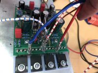
The EXC20N10 and ECX20P10 are used as you can see on the photo.
The supplied pcb is perfectly usable with 2 really small artwork changes and The correct orientation of the parts.
As i stated before, the deal is that ill send new pcb’s for half the price + shipping for those that bought the first version.
The updated doc will be with the new pcb’s. The doc you received is the original doc from Hawk as delivered to me. It is not poor and when you spend some time you will be able to build a working amplifier with very nice performance that is out there with the very best amps that i know.
The EXC20N10 and ECX20P10 are used as you can see on the photo.
The supplied pcb is perfectly usable with 2 really small artwork changes and The correct orientation of the parts.
As i stated before, the deal is that ill send new pcb’s for half the price + shipping for those that bought the first version.
Dear Marcel,
In answer to post 170 ;
In the files that were included with the boards I saw on the drawing of their board that Hawk Audio, just like you, only used 1 resistor and 1 capacitor on the cathode of the BD140, and none on te BD139. So I am satisfied. By the way, there was a small error in your schematic ; for the positive voltage to the opamp are the zenerdiode and capacitor upside down.
Dear Jurjen,
The zener is correctly implemented on both versions of the pcb.
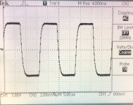
I also looked at the a version with 2 collector resistors and 2 caps and tested in real life. with 2 resistors the dynamics is a tad lower and the BW is a bit lower as well. Tot that that matters a lot as the 60KHz square wave was still quite nice.
This afternoon I get a better BNC cable so the noise on the signal will be way less.
The zener is correctly implemented on both versions of the pcb.
I also looked at the a version with 2 collector resistors and 2 caps and tested in real life. with 2 resistors the dynamics is a tad lower and the BW is a bit lower as well. Tot that that matters a lot as the 60KHz square wave was still quite nice.
This afternoon I get a better BNC cable so the noise on the signal will be way less.
Glad to see everything is working and that you are proud of your work. Is someone else also checking your boards ? And maybe to soon to ask ; when can we order them ? Instead of the 4 that I ordered earlier, this time I would like to order 8 of them, and for the full price.
Good luck finishing the last details.
Greetings from a wet, wet, wet Holland.
Good luck finishing the last details.
Greetings from a wet, wet, wet Holland.
- Home
- Group Buys
- PCB for the HAWK A18 amplifier (+ FETs if required)