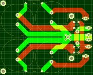
This is the new version of the board. It takes both the Exicon and Toshiba fets. It is also designed to handle slightly higher power rails.
Hi Marcel.
You mention in a pm that this PSU pcb can mount on the top of the AMP pcb - how does this happen, thanks?
You mention in a pm that this PSU pcb can mount on the top of the AMP pcb - how does this happen, thanks?
Via the 4 mounting holes and M3 distance pillars. The connections for the supply voltage and the ground also line up and this way the distance to the power caps is short.
Thanks Marcel for the service you give us.
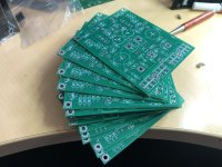
I am curious of how you solved the problem of replacing the 7812 and 7912. Looking at the board you used a discrete solution ; I see a lot of extra small transistors. Do you give us a list of components as well as a schematic with the boards ? I can't wait
I am curious of how you solved the problem of replacing the 7812 and 7912. Looking at the board you used a discrete solution ; I see a lot of extra small transistors. Do you give us a list of components as well as a schematic with the boards ? I can't wait
Also , many thanks Marcel for the great service.
@Jurjen1965, Marcel assures me all the documentation will come with your pcb's.
@Jurjen1965, Marcel assures me all the documentation will come with your pcb's.
Marcel,
Have you verified the new board layout with discrete regulation works correctly and is without component errors?
Have you verified the new board layout with discrete regulation works correctly and is without component errors?
Hi Marcel. Do you still have boards left for a stereo version ? I would take a set.
Best regards
Christoph
Best regards
Christoph
Well Vunce, nice to hear from you. I see the seller has not responded here in this thread - but I can add something. I know you are not the 1st person to ask about the discreet regulation and I have not seen any response to that from Marcel. With regards to the second part of your question - I can help out members here as I ordered a set of boards as per posts #116, then post #122 where Marcel says the board was checked.
Then I got some PM's from him after the boards were shipped as below:
Gary,
There is an error in the orientation of the bc transistors, the lm329 and the j 112.
So pls chek the orientation before placing the components
Regards,
Marcel
I sent Marcel a PM and asked:
How many components in total have the wrong orientation, as I don't have any documentation and I assume the documentation you sent with the pcb's will not have these corrected updates, it is essential you email me the clear details on every component that is wrong and how they should be inserted in the pcb for correct operation - you obviously need to send this to the other members who purchased the pcb's.
Are you going to correct these mistakes and send new pcb's out?
Marcel's answer:
Q1, Q3, Q2, Q4, Q5, Q6, Q7, Q8, Q11, Q13, ZD1, Q14 en ZD2 need to be rotated 180 degrees. Sthey will still fit the PCB.
So there are at least 13 component orientation errors on this new pcb, and he has asked me to check once I receive the pcb's and documentation to see if I find any more.
You will notice he has gone silent in the tread - so I would be very wary with this.
If you look back earlier in the thread, you will see he made the same type of mistakes in the 1st design, which I might add were highlighted by another member and not Marcel himself.
Overall a very bad experience, buyer beware!!!!

I answered one of your questions Vunce - now we wait to see if Marcel can answer the 1st part of your question in post # 132.

Unfortunate there are some small errors in the silkscreen. Gary forwarded the specifics. There is also a small error in the pinout of the 2 fets in the voltage stabilizers and the track layout. This is because i mixed up the j112 originally specified and the 2sk246 that i intend to use.
Marcel,
So everyone is clear on this. Please list every component that is affected and what needs to be done to have it inserted correctly in the pcb.
I am not sure what you mean about the 2 fets - are these ZD1 and ZD2 you mentioned to me?
So everyone is clear on this. Please list every component that is affected and what needs to be done to have it inserted correctly in the pcb.
I am not sure what you mean about the 2 fets - are these ZD1 and ZD2 you mentioned to me?
I think he means Q15 and Q16, both are J112 JFET's , as mentioned in the file send along with the boards.
- Home
- Group Buys
- PCB for the HAWK A18 amplifier (+ FETs if required)