[QUOTE
As this thread's audience is full of experts I would like to post a link to another power follower (and I do not pretend to hijack this thread, please) with another topology, that could be interesting, and in the mood to learn the basics of these circuit's function.
the Power Folllower
Dear Shaan, I will use a PowerReg type of capacitance multiplier supply:
Introducing the PowerReg - pink fish media
Hello
Did someone try these amplifier ?
I think these Power Follower from Andrea is worth a try.
Any opinion ...
Greets
Happy New Year
Hello there.
Looks like you copy-pasted the old post again. Well, If you really are interested in the amp in your post then please create a new thread for it. I think everyone will appreciate if you do so and will definitely share their thoughts with you. It's very easy to make a new thread. Yes this thread and its audience are full of experts(me not one) and I believe they helps anyone if they are asked in the right way. I've seen the schematic in your post beforehand and do think many people in diyAudio are using it. But you see, If you create a new thread dedicated to that amp and use it's name as the thread's name then it will be shown to more people at any time. They don't have to click on this thread for it. Things will be done easily and quickly.
Thanks and Happy New Year.
Last edited:
Hello shaan
Yes you right , originally the schematic was posted by Maxlorenz ...
I sow it here so I thought I ask first here if is worth to try these amp ..
I do not want to hijack your tread , please forgive me . I'm not sure if these amplifier schematic worth to start a new tread .
I hope PMA can give me some idea .He is a expert guy , I learn a lot from him just read his posts .
Regards
I will build Andrea's Power buffer...after PMA's, Triphon amp, Pass' J2, DX Blame ES, Pass' Delite... 😛
In fact, I will build two kind of power supplies (for two different kind of amps) and then swap amplifier modules-> PMA's, Andrea's and Pass Delite on one type of PS, and Triphon and Pass J2 in a couple of monoblocks...
Cheers,
M
In fact, I will build two kind of power supplies (for two different kind of amps) and then swap amplifier modules-> PMA's, Andrea's and Pass Delite on one type of PS, and Triphon and Pass J2 in a couple of monoblocks...
Cheers,
M
Hello shaan
Yes you right , originally the schematic was posted by Maxlorenz ...
I sow it here so I thought I ask first here if is worth to try these amp ..
I do not want to hijack your tread , please forgive me . I'm not sure if these amplifier schematic worth to start a new tread .
I hope PMA can give me some idea .He is a expert guy , I learn a lot from him just read his posts .
Regards
I see.
There is a thread dedicated to Andrea's follower http://www.diyaudio.com/forums/solid-state/3471-andrea-ciuffolis-power-follower.html but seems to be very old. You may care to give it a kick start if you are not sure whether to start a new thread. I don't think moderators will raid your account for that. 🙂 There are three threads on Pavel's follower, all alive.
There is another way which I think is better, that is, PM Pavel directly with your questions. He's a nice guy and I'm sure he'll hear your say.
shaan
Last edited:
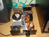
Photo of my build. Finally a Pure MOSFET Follower. LOL
Hello Everyone!
So, here it is. New MPF with FET Current Source(Sink). Actually the old MPF with ONLY the darlington replaced by a MOSFET. The gate stopper is default 270 ohms as was in the original with No oscillation for 8 days! 😀 😎
The TIP3055 BJTs seen were used in the DOZ power amp I made and dismissed. 😉
My cam is film based so had to borrow a digital one from my friend. Sorry for the delay.
Attachments

The connections are made exactly as the picture shown in the very first post of this thread. I wonder what made it oscillate so bad then. I think there was some wiring mistake.
An externally hosted image should be here but it was not working when we last tested it.
Last edited:
Shaan,
these sorts of circuits sound very good with tube front end. A reasonably beefy triode, something like a 6DJ8 operating at 15mA, would drive the gate of the upper mosfet through a 0.47uF quality filmcap very nicely. I'd suggest a B+ on the 6DJ8 of about 150V, should be more than enough.
This will give a tube overlay to the sound, which from your circuit is fairly neutral, with H2and H3 predominating.
Why not try it - it's instructive to see how a tube sounds in this application.
Hugh
Member
Joined 2009
Paid Member
The connections are made exactly as the picture shown ..
I like this circuit, but it has relatively poor PSRR, the psu will need to be designed appropriately.
Gareth,
All SE circuits have the PSRR problem, but the source follower is better than most....
Don't let this discourage you, a simple CLC is all you need.
Hugh
All SE circuits have the PSRR problem, but the source follower is better than most....
Don't let this discourage you, a simple CLC is all you need.
Hugh
Member
Joined 2009
Paid Member
OR, you can use lots of nfb and the PSRR problem goes away 😀
p.s. I will be using CLC, common choke, as recommended by you of course !
First I have to get off the couch, stop playing with Spice and start building the boxes. I will have cut up some heatsink and some plywood and do something useful with them. A couple of weeks of bruised knuckles and cut fingers should get me somewhere I hope.
Last edited:
Shaan,
these sorts of circuits sound very good with tube front end. A reasonably beefy triode, something like a 6DJ8 operating at 15mA, would drive the gate of the upper mosfet through a 0.47uF quality filmcap very nicely. I'd suggest a B+ on the 6DJ8 of about 150V, should be more than enough.
This will give a tube overlay to the sound, which from your circuit is fairly neutral, with H2and H3 predominating.
Why not try it - it's instructive to see how a tube sounds in this application.
Hugh
hi AKSA
Yup that's already on my mind, but I need some more knowledge about tubes before buying one. I believe within a year I will be working with tubes, preferably for preamp, 'followed' by some follower, maybe. 🙂
shaan
I like this circuit, but it has relatively poor PSRR, the psu will need to be designed appropriately.
Hi Bigun!
This is the case with most(if not all) Class-A designs, that's why there is a Capacitance multiplier here. Connected in series with the supply this only dissipates about a couple of watts. But, all PSRR problems are solved with a $5 circuit. Better than a 33000uF cap. Yes. Truly cheap, truly wonderful. Give it a try if you haven't already.
Link-> Capacitance Multiplier Power Supply Filter
Member
Joined 2009
Paid Member
I do like the cap multiplier and have been playing with this. My thoughts are that the cap multiplier should be the same high quality pass transistor as the amplifier output devices because the signal will flow through it. It should also be the same topology, so if your output is a simple source follower then your cap multiplier will be too. If you output if Sziklai, then your cap multiplier is too.
It still helps to have a high capacitance in the psu unless you are running constant current Class A - which I think you are if I remember.
It still helps to have a high capacitance in the psu unless you are running constant current Class A - which I think you are if I remember.
I do like the cap multiplier and have been playing with this. My thoughts are that the cap multiplier should be the same high quality pass transistor as the amplifier output devices because the signal will flow through it. It should also be the same topology, so if your output is a simple source follower then your cap multiplier will be too. If you output if Sziklai, then your cap multiplier is too.
It still helps to have a high capacitance in the psu unless you are running constant current Class A - which I think you are if I remember.
My Cap multiplier is darlington. Anyway, one can put a 4700uF in the output of the cap multiplier if class-ab is what we think of, and place a high current diode parallel with the multiplier transistors in opposite electrical direction to prevent reverse biasing at power off. Still cheaper than a 33KuF! 😀 Well, when we really need the advantages of class-ab, then thinking about the multiplier is just wasting time, big cappy is the clean winner. AB's got BIG PSRR. 😀
My case is not class-ab, however, I am using the multiplier with a 1000uF in its output and a protection diode too. The multiplier devices don't burn for the momentary short caused by the 1000uF cap; it has two power transistors in parallel. Peace.
I do like the cap multiplier and have been playing with this. My thoughts are that the cap multiplier should be the same high quality pass transistor as the amplifier output devices because the signal will flow through it. It should also be the same topology, so if your output is a simple source follower then your cap multiplier will be too. If you output if Sziklai, then your cap multiplier is too.
Why? It's like saying that the drivers should be the same transistors as used in the OPs. it doesnt make sense to me. (i'm generalizing to any amp)
Also, are you sure that it's in the signal path?
Thanks!
Quoting my own message 😛. This is the first post of this thread where the schematic shown was tried by myself and was found to be working.
A lot of discussions have been done on it and I thank everyone who contributed to this.
After an entire month of experiment and knowledge gathering I have seen that the configuration shown in that post is quite stable without any ill effects like RF oscillation or higher distortion in output. The situation was same at the first week of December 2K9 when I first replaced the darlington with a FET, out of pure curiousity.
I remember the RF oscillation started at the very moment I put a resistor in the gate of the CCS MOSFET.
Now, the resistor at the gate of the upper MOSFET is still 270ohm and is fine. I tested the follower with IRFP240, IRFP150N and recently IRF540N😀😱, all of which worked fine with the default 270ohm. All the Zenners are on the board(not on heatsinks) so the current rises slightly after half an hour of operation or so; the meter shows it to be around 100mA more than the initial value. But, this was also the same case with the darlington so this does not seem to cause a serious problem, although with darlington the increase in current was lower, about 40-50mA.
So, under the light of the above-mentioned condition I decided to make the schematic The Final One for me and will build it as shown.
The Follower:-
Thanks again to everyone who posted and helped.
Hello everyone.
A few months ago I made a couple of the follower and everything was good. Its current source is based on the NPN darlington TIP142, which is getting increasingly harder to find here. Soon I think it will become a totally unavailable antique discrete. If the ones installed ever die after say 2 or 3 years, I don't know what I'll do.
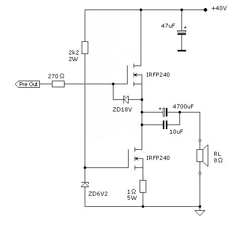
In the shadow of the above-mentioned condition of the darlington, I thought how would it be if the CCS was also made of a MOSFET.
MOSFETs are fast. Appealing. I tried it, with an IRFP240 replacing the darlington's collector, base and emitter with drain, gate and source respectively. And for the zenner diode I used a 6V2 one instead of the default 3V3.
Before testing I ran a simulation and the config was a success. However, the simulator's current probe does not show quiescent current through them; don't know why. I'm complete newbie in the sim field.
I tried it with the changed config and at the time of writing this it's running quite good for about 8 hours since noon. Quiescent current is about 2.5 Amps. No sign of instability and/or oscillation. It's drawing pretty much the same power from the PS as it did with the darlington. It's also making the same noise(music) as loud and as tight as the previous. To say the truth the sound is little different from ago with nicer sounding highs, the sound is just different.
But that's all I could see through my ears, as I don't have sophisticated measuring instruments.
So, I humbly request PMA and all the interested and kind hearted people to give this a little of their precious time and let us know the details of the tests.
This is what the modified schematic looks like:-
Thanks
.
Quoting my own message 😛. This is the first post of this thread where the schematic shown was tried by myself and was found to be working.
A lot of discussions have been done on it and I thank everyone who contributed to this.
After an entire month of experiment and knowledge gathering I have seen that the configuration shown in that post is quite stable without any ill effects like RF oscillation or higher distortion in output. The situation was same at the first week of December 2K9 when I first replaced the darlington with a FET, out of pure curiousity.
I remember the RF oscillation started at the very moment I put a resistor in the gate of the CCS MOSFET.
Now, the resistor at the gate of the upper MOSFET is still 270ohm and is fine. I tested the follower with IRFP240, IRFP150N and recently IRF540N😀😱, all of which worked fine with the default 270ohm. All the Zenners are on the board(not on heatsinks) so the current rises slightly after half an hour of operation or so; the meter shows it to be around 100mA more than the initial value. But, this was also the same case with the darlington so this does not seem to cause a serious problem, although with darlington the increase in current was lower, about 40-50mA.
So, under the light of the above-mentioned condition I decided to make the schematic The Final One for me and will build it as shown.
The Follower:-
An externally hosted image should be here but it was not working when we last tested it.
Thanks again to everyone who posted and helped.
Shaan,
You can slightly improve rail efficiency by reducing the voltage of the Zener and the source resistor. I have found things utterly stable with the loss of only 1.5V of negative signal excursion by dropping the zener to 4.2V (two green LEDs operating at about 10mA) and the resistor to 0.235 (two 0R47 in parallel).
This will give a couple more volts of negative swing, quite useful. You can then bias the upper device at a calibrated voltage so that clip is symmetrical. At a guess you should get around 36Vpp from this circuit, corresponding to 20 watts into 8R. You will need 18/8 = 2.25A plus a 12% margin on the CCS, that is, 2.5A, to handle any load.
Cheers,
Hugh
Member
Joined 2009
Paid Member
Why? It's like saying that the drivers should be the same transistors as used in the OPs. it doesnt make sense to me. (i'm generalizing to any amp)
Also, are you sure that it's in the signal path?
You're right, it's a philosophical point of view that there should be a match up in topology and devices if the signal is going through them all.
But I do believe that the signal goes through the cap multiplier. The output signal flows in a complete circuit - by definition. It flows through the output devices and the speaker but the circuit is completed by the power supply. We usually like to think that the 'last capacitor' of the power supply is the ac signal path through the power supply because at audio frequencies the transformer is off limits, isolated by the rectifier diodes.
But we have replaced this 'last capacitor' by a capacitance multiplier and so the signal must flow through it.
You can try putting a decoupling cap across the multiplier, but it will only get the bulk of the signal current if it has an impedance much lower than that of the cap multiplier that it is in parallel with. Since the cap multiplier is designed to have a low output impedance this would require a very large capacitor. In fact it would have to be a larger capacitor than the effective capacitance of the cap multiplier - completely defeating the whole point of using a capacitance multiplier.
So yes, definitely the signal will go through the capacitance multiplier - no doubt about it. This isn't necessarily a bad thing - the signal afterall has to go through the power supply and perhaps the pass device of the capacitance multiplier is preferred to a real capacitor - people seem to have a 'thing' for capacitors in the signal path. Going to split rails to eliminate an output capacitor only gets you half way there, but going with split rails and using a cap multiplier gets you much further. Nobody does that though.
I think the only downside to using a cap multiplier is another set of components and heatsinking which is more faff. AKSA has told me in the past that he doesn't like capacitance multipliers - doesn't like the 'sound'. This is something to be afraid of because AKSA has a lot of experience with this kind of thing. So one may conclude that the non-linearities of the pass device are ultimately worse than a capacitor. Unfortunately, that still leaves you with a couple of devices in the signal flow- the amplifier output !!!!
Last edited:
I have tried cap multipliers, and while they deliver low ripple, the foregoing post is correct and signal does flow through them, in one direction, obviously.
Listening tests between CRC and cap multipliers showed some sonic differences. I felt that the cap mult measured better (lower ripple, lower ESR) but the the CRC sounded better. These conclusions sit uncomfortably with me but there it is.
Hugh
Listening tests between CRC and cap multipliers showed some sonic differences. I felt that the cap mult measured better (lower ripple, lower ESR) but the the CRC sounded better. These conclusions sit uncomfortably with me but there it is.
Hugh
So yes, definitely the signal will go through the capacitance multiplier - no doubt about it. This isn't necessarily a bad thing - the signal afterall has to go through the power supply and perhaps the pass device of the capacitance multiplier is preferred to a real capacitor - people seem to have a 'thing' for capacitors in the signal path. Going to split rails to eliminate an output capacitor only gets you half way there, but going with split rails and using a cap multiplier gets you much further. Nobody does that though.
Hey, I was just going to try just that! 😀
I think the only downside to using a cap multiplier is another set of components and heatsinking which is more faff. AKSA has told me in the past that he doesn't like capacitance multipliers - doesn't like the 'sound'. This is something to be afraid of because AKSA has a lot of experience with this kind of thing. So one may conclude that the non-linearities of the pass device are ultimately worse than a capacitor. Unfortunately, that still leaves you with a couple of devices in the signal flow- the amplifier output !!!!
It's disturbing when poorer measured circuits sound better. It definitely makes you wonder which are the things that we are NOT measuring.
AKSA (thanks!), did you try both class A and AB setups in comparing cap multi to CRC?
- Status
- Not open for further replies.
- Home
- Amplifiers
- Solid State
- Pavel's MOSFET Follower - No Darlington Mod