Shaan what simualation software are you using?
Simetrix intro. V5 probably.
Yes!
Hello everyone! Hi Pavel!
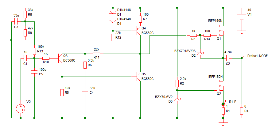
The circuit is happily working with both the resistors in the gate of the upper FET. There is NO sonic degradation in the output and the circuit is stable in real world. It's been running for 10 hours since yesterday. Non stop.
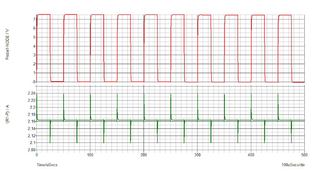
Below are the schematic and simulation results of 20 kilohertz squarewave response with current variation in the CCS load resistor.
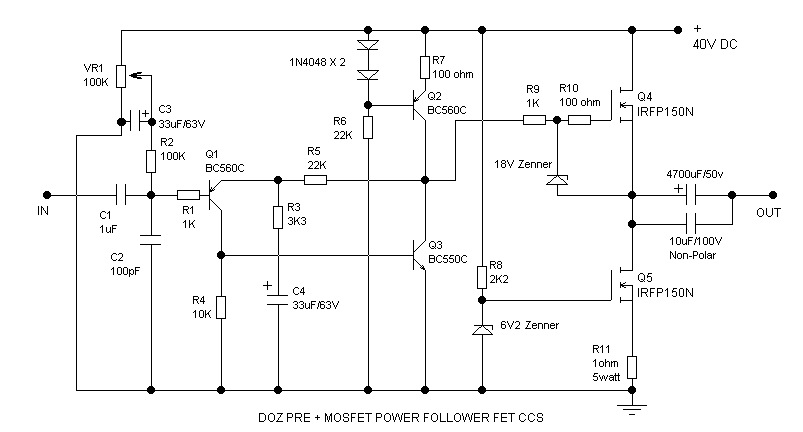
The Schematic
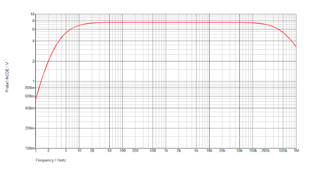
Frequency Response
20KHz Squarewave Test
I think this circuit will work for most people. Please leave your responses.
BIG Thanks.
IT'S WORKING!
Hello everyone! Hi Pavel!
The circuit is happily working with both the resistors in the gate of the upper FET. There is NO sonic degradation in the output and the circuit is stable in real world. It's been running for 10 hours since yesterday. Non stop.
Below are the schematic and simulation results of 20 kilohertz squarewave response with current variation in the CCS load resistor.
The Schematic
Frequency Response
20KHz Squarewave Test
I think this circuit will work for most people. Please leave your responses.
BIG Thanks.
Last edited:
shaan -
thank you for your feedback. Such posts are awards for us who try to help and to build working amplifiers for wide community of diyers.
And congratulations for your perfect work.
Best,
thank you for your feedback. Such posts are awards for us who try to help and to build working amplifiers for wide community of diyers.
And congratulations for your perfect work.
Best,
Last edited:
Hi Pavel.
This circuit was possible for the greatly helpful advices and useful informations you provided throughout the thread. I really learned a lot in the last few days and that was what gave me confidence. So, Thanks a LOT!
Thanks to everyone who posted in this thread and shared their thoughts with open hearts. I now feel like a part of the diyAudio community for real.
You might like to ask Rod Elliot to update the Project 83? He is a very nice guy and would communicate with you IMO.
Hi Pavel.
I believe he will check the schematic. But, he's generally not much into Class-A and even less into FET output stages. 😀 This makes me a little scared. But of course I will talk with him about it.
Thanks.
I believe he will check the schematic. But, he's generally not much into Class-A and even less into FET output stages. 😀 This makes me a little scared. But of course I will talk with him about it.
Thanks.
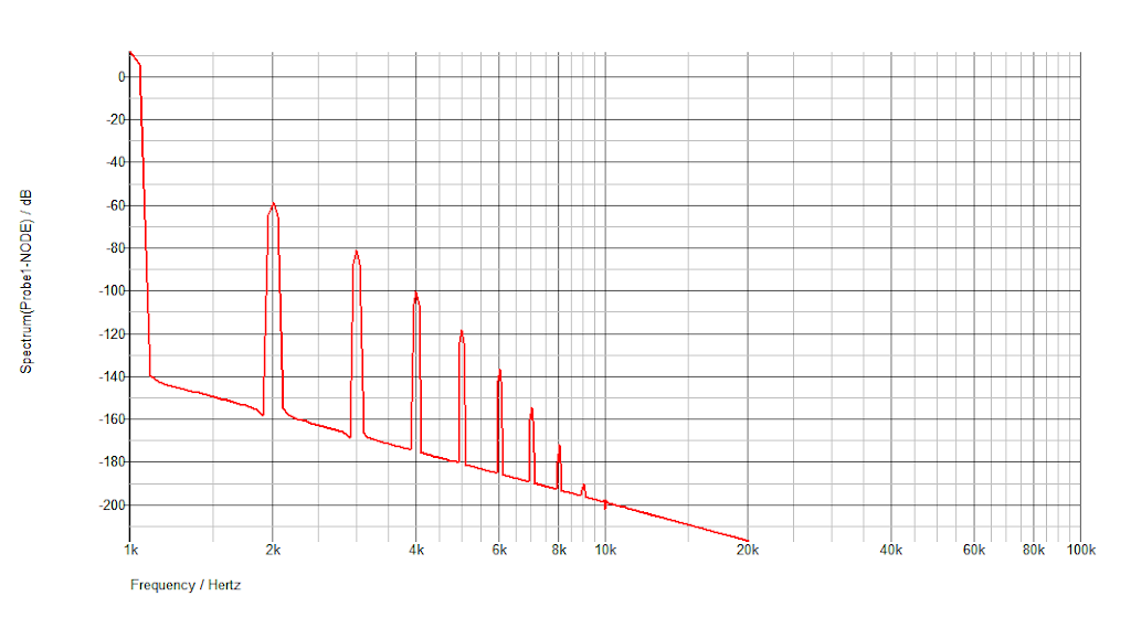
Fourier spectrum of 1KHz sinewave of the DoZ preamp + Pure MOSFET Follower. (Is it okay if I call it "Pure MOSFET Follower" or PMF? 🙂 )
Is this what we call "Monotonically Decaying Harmonic Spectrum"? If we do, then this amp is a GEM.
Thanks.
Low power
Full Power
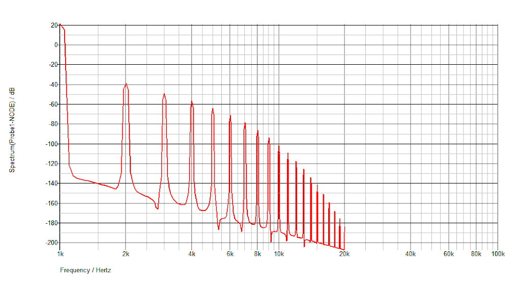
Full Power
Is this what we call "Monotonically Decaying Harmonic Spectrum"? If we do, then this amp is a GEM.
Thanks.
Last edited:
Congratulation Shaan,
If you could actually drive the amp with 10 Khz square wave and get a scope to see , it would show the actual behaviour - better than simulation. a photo of your build will also be nice to see!
kannan
If you could actually drive the amp with 10 Khz square wave and get a scope to see , it would show the actual behaviour - better than simulation. a photo of your build will also be nice to see!
kannan
Congratulation Shaan,
If you could actually drive the amp with 10 Khz square wave and get a scope to see , it would show the actual behaviour - better than simulation. a photo of your build will also be nice to see!
kannan
Thanks kannan.
I have a 10khz sqr wave source but no scope. Those who have both and also like this circuit are requested to help. I will post my rig's photo soon.
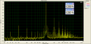
These is the real world, 5W into 10 ohm. Power supply intermodulation lines would vanish with regulated PSU, I had only 5000 uF filter cap.
Hi Pavel.
What would possibly be the visible change in that spectra with a capacitance multiplier; to say, with a very clean power supply? What are the PS intermodulation lines? The low magnitude lines between the harmonics?
Thanks.
Understood.
Is this the spectra of the fet ccs mpf? If so, then what would be your comment on 0.24% of THD+N at 5 watt? Low, medium or high?
Thanks.
Is this the spectra of the fet ccs mpf? If so, then what would be your comment on 0.24% of THD+N at 5 watt? Low, medium or high?
Thanks.
Last edited:
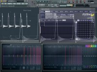
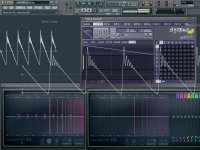
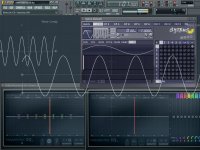
I was wondering how I could actually watch the waveform without a physical oscilloscope. The web provided me with many, but I didn't find any easy to use. So chose FL Studio's inbuilt plugins and monitors and did some "watch" job on the output, my way.
In every case a 1KHz signal(sine, triangle, sawtooth, square and impulse) was generated from the horribly unfit for the job "Sytrus" plugin and sent to line-out. The amp was fed from line-out and set at a power of about 5-6 watts in an 8 ohm load. The output was also connected to the line-in and then FL Studio's mixer was fed the return signal from line-in. An oscilloscope(wavecandy) and a specrtrum analyzer(parametric EQ 2) was placed in both the line-out and line-in. The line-in's return was not channeled to the master as it would cause feedback.
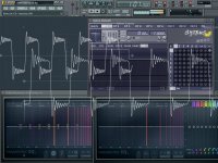
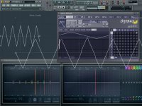
The Sytrus plugin(the one with a thousand volume controls 🙂 ) shows in a window what the output waveform "should be" while the smaller oscilloscope in the left shows the "actual" waveshape fed to the line-out. The larger oscilloscope shows the return signal from the amplifier's output. The two spectrum analyzers(bottom) shows the spectrum of the line-out(left spectrum) and amplifier return(right spectrum).
Now, all these software plugins are ridiculously inaccurate and the difference between the "should be" and "actual" waveforms shows it clearly. But, I looked at and compared the two oscilloscope's waveforms and tried to figure out how much "honest" the follower is to the signal at its input. And it looks like it is not as bad as I thought it was. Though the waveforms seen in the oscilloscopes looks quite different from what the plugin shows it "should be", the difference between the two oscilloscope's wave shape is almost identical in all the cases(in case of the sine wave it's just exact replica of the input).
The spectrum analyzers do not actually show's the harmonics in dB or V, instead shows them in bands of color, very bright yellow for high amount and red to dark red for lower values. Again, these were chosen to just see how much similarity exists between the input and the output, complementing the oscilloscopes.
All noobwork though.
The pictures are sorted this way- impulse, sawtooth, sine, square and triangle.
Thanks.
In every case a 1KHz signal(sine, triangle, sawtooth, square and impulse) was generated from the horribly unfit for the job "Sytrus" plugin and sent to line-out. The amp was fed from line-out and set at a power of about 5-6 watts in an 8 ohm load. The output was also connected to the line-in and then FL Studio's mixer was fed the return signal from line-in. An oscilloscope(wavecandy) and a specrtrum analyzer(parametric EQ 2) was placed in both the line-out and line-in. The line-in's return was not channeled to the master as it would cause feedback.
The Sytrus plugin(the one with a thousand volume controls 🙂 ) shows in a window what the output waveform "should be" while the smaller oscilloscope in the left shows the "actual" waveshape fed to the line-out. The larger oscilloscope shows the return signal from the amplifier's output. The two spectrum analyzers(bottom) shows the spectrum of the line-out(left spectrum) and amplifier return(right spectrum).
Now, all these software plugins are ridiculously inaccurate and the difference between the "should be" and "actual" waveforms shows it clearly. But, I looked at and compared the two oscilloscope's waveforms and tried to figure out how much "honest" the follower is to the signal at its input. And it looks like it is not as bad as I thought it was. Though the waveforms seen in the oscilloscopes looks quite different from what the plugin shows it "should be", the difference between the two oscilloscope's wave shape is almost identical in all the cases(in case of the sine wave it's just exact replica of the input).
The spectrum analyzers do not actually show's the harmonics in dB or V, instead shows them in bands of color, very bright yellow for high amount and red to dark red for lower values. Again, these were chosen to just see how much similarity exists between the input and the output, complementing the oscilloscopes.
All noobwork though.
The pictures are sorted this way- impulse, sawtooth, sine, square and triangle.
Thanks.
An externally hosted image should be here but it was not working when we last tested it.
Attachments
Last edited:
This was for BJT CCS.
I see. This topology indeed does what it says.
shaan, you seem to become a Master pretty fast, so you do not need any more advices. Probably my last ones:
1) distortion with BJT CCS and MOSFET CCS is almost same,
2) please do not use squares, triangles and sawtooths generated by audio soundcard. They are slow - sharply bandlimited at Fs/2 (half of sampling frequency). Thus, you get oscillating responses with slow rise time, as a result of sharp lowpass filters.
shaan, you seem to become a Master pretty fast, so you do not need any more advices. Probably my last ones:
That's not true.
1) distortion with BJT CCS and MOSFET CCS is almost same,
Thanks. This really makes a lot of work easy!
2) please do not use squares, triangles and sawtooths generated by audio soundcard. They are slow - sharply bandlimited at Fs/2 (half of sampling frequency). Thus, you get oscillating responses with slow rise time, as a result of sharp lowpass filters.
Understood. Thanks for the info.
[QUOTE
As this thread's audience is full of experts I would like to post a link to another power follower (and I do not pretend to hijack this thread, please) with another topology, that could be interesting, and in the mood to learn the basics of these circuit's function.
the Power Folllower
Dear Shaan, I will use a PowerReg type of capacitance multiplier supply:
Introducing the PowerReg - pink fish media
Hello
Did someone try these amplifier ?
I think these Power Follower from Andrea is worth a try.
Any opinion ...
Greets
Happy New Year
Attachments
Last edited:
- Status
- Not open for further replies.
- Home
- Amplifiers
- Solid State
- Pavel's MOSFET Follower - No Darlington Mod