wahab,
I`ve never ever said that. Sonically, nothing beats the single-ended mode.
Zenotron?
i keep my doubts about the so called superiority of the single
ended mode...a classA PP exhibits the same qualities,
minus the highTHD and low yeld...
zenotron?..what s that? a design of yours?..
no, i use a complementary differential + vas + lateral fet
whose general design philosophy is at odd with many guidelines,
including my habitual ones...
wahab,
you could definitely dismiss your doubts, push-pull cannot compete with the single-ended mode.
Zenotron is a French design:
i did build one, though the name was profet at the time..
i used three devices per rail, the ancestors of the ones in
your schematic, aka 2SJ48/2SK133, the 120V low grade of
the 160V 2SK50/2SK135....
later, i did cannibalize the lateral fets to build another amp
which ,to my hearing, sound better...so much better..
btw, lumba, is that your current amp?...or have you one
of those fire place replacements, i mean a single ended design?..
I doubt he does. However, I think he has much better than this SE thing or whatever. Multi Ended may be. So mysterious. I'm definitely following the story.
new name?
b.t.w. People, what would we call this "soon to be born" new follower? Just a thought.🙂
PMA is hereby requested to make the final decision on the new name and/or whether there will be a new name at all.😀
Inputs are welcome!
"MPF v2" is my preference.😀
thanks.
b.t.w. People, what would we call this "soon to be born" new follower? Just a thought.🙂
PMA is hereby requested to make the final decision on the new name and/or whether there will be a new name at all.😀
Inputs are welcome!
"MPF v2" is my preference.😀
thanks.
shaan,
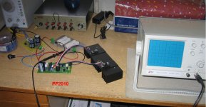
just screwing TO3-P packages onto heatsink 😉
WOW!!!!!!!
I'll be hearing.
All the best!
thanks.
MOSFETs have one principal advantage over BJTs in this sort of application - no secondary breakdown, i.e. as Hugh said, better thermal robustness.
They, however have a lot of issues that can be solved, but you should not take the MOSFET for granted:
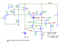
1) Predictability of current versus the gate reference is worse, because treshold voltages vary much more than the proverbial Vbe of bipolars. From this standpoint, the current source shown by Lumba Ogir is more precise. However, it's a two-device feedback system, so 180deg phase shift = oscillation, is possible even if the devices were perfectly first order (and they are not). The cure is putting a capacitor across C-E of the control BJT, but see below.
2) Cgd is a real issue. Because it's non-linear, it changes the transient behaviour of the CCS with amplitude. When Vds becomes low, about 5-10V depending on the type of MOSFET, it rises quite abruptly. This means that the spikes shown by PMA become higher for output signal amplitudes closer to the maximum, and indeed very high at clipping. Again, a lower gate stopper and capacitor mentioned above can reduce this.
Because of this it's actually quite difficult to make a good MOSFET CCS for HF - lots of residual capacitance. Fortunately, since it's driven from a follower, it's not a great issue, but it is there.
3) Wiring and layout are critical, as well as some part selections - for instance, consider wire or resistor inductances in the gate line - charging and discharging Cgd will be greatly slowed down (spikes!) if these are excessive. Now, consider an inductive resistor in the source - if you have considered carefully, you may notice that it may not be the best policy to use perfect noninductive resistors everywhere!
4) MOSFETs can work down to Vds near zero volts. At first looks, this is very nice, but be advised that the reverse capacitance issue actually may result in the output of the follower 'sticking' to the ground rail when it clips, in feedback CCS types like Lumba showed. The feedback will try to increase Vgs in order to attempt a constant current with 'no voltage left' across the MOSFET and it's current sense resistor. This will charge the input capacitance (now grown due to low Vds) to a much higher voltage than at normal conditions. Once the input of the follower starts rising, it will take a lot of time to discharge Cgs||Cgd through the gate stopper, resulting in a transient in current. There is no simple and complete cure but keeping things simple, there are two strategies to reduce the problem:
a) Chose a MOSFET with lower Gm and appropriate current, voltage and power dissipation capability in order to minimize Cgs and Cgd. For instance, DO NOT use a random part from the bin, say a 40A part for a 2A current sink - when a 10A part will suffice, because the 10A part will likely have 1/4 of Cgs and Cgd (remember, this is a CCS so it's maximum current is 'constant' - no need for much headroom). Because transconductance is lower, it will require a little more Vgs to get the desired current, lowering somewhat the output voltage swing before the nonlinearity of Cgd becomes a serious issue - but this is likely to only be a volt or two for a 4-fold reduction in capacitances.
b) Use a clamp to prevent the gate voltage from getting out of hand. Simplest is a zener to ground, a bit more complex a diode string to the output (drain) of the sink. The current spike will remain as you must have some overhead for maximum gate voltage to account for MOSFET, temperature and clamp tolerance variations, but it can be signifficantly reduced.
A final word should be said about simulations of such circuits. When simulating with square waves at the input, the generator should be set up with realistic rise and fall times. By default, these are very steep, far steeper than real life - and if such were present in real life, cable effects would be a problem before spikes in the current source would. Also, be mindful of MOSFET models - these tend to be notoriously bad, amongst other things, capacitance nonlinearity is poorely modeled, and in some cases, not at all.
They, however have a lot of issues that can be solved, but you should not take the MOSFET for granted:
1) Predictability of current versus the gate reference is worse, because treshold voltages vary much more than the proverbial Vbe of bipolars. From this standpoint, the current source shown by Lumba Ogir is more precise. However, it's a two-device feedback system, so 180deg phase shift = oscillation, is possible even if the devices were perfectly first order (and they are not). The cure is putting a capacitor across C-E of the control BJT, but see below.
2) Cgd is a real issue. Because it's non-linear, it changes the transient behaviour of the CCS with amplitude. When Vds becomes low, about 5-10V depending on the type of MOSFET, it rises quite abruptly. This means that the spikes shown by PMA become higher for output signal amplitudes closer to the maximum, and indeed very high at clipping. Again, a lower gate stopper and capacitor mentioned above can reduce this.
Because of this it's actually quite difficult to make a good MOSFET CCS for HF - lots of residual capacitance. Fortunately, since it's driven from a follower, it's not a great issue, but it is there.
3) Wiring and layout are critical, as well as some part selections - for instance, consider wire or resistor inductances in the gate line - charging and discharging Cgd will be greatly slowed down (spikes!) if these are excessive. Now, consider an inductive resistor in the source - if you have considered carefully, you may notice that it may not be the best policy to use perfect noninductive resistors everywhere!
4) MOSFETs can work down to Vds near zero volts. At first looks, this is very nice, but be advised that the reverse capacitance issue actually may result in the output of the follower 'sticking' to the ground rail when it clips, in feedback CCS types like Lumba showed. The feedback will try to increase Vgs in order to attempt a constant current with 'no voltage left' across the MOSFET and it's current sense resistor. This will charge the input capacitance (now grown due to low Vds) to a much higher voltage than at normal conditions. Once the input of the follower starts rising, it will take a lot of time to discharge Cgs||Cgd through the gate stopper, resulting in a transient in current. There is no simple and complete cure but keeping things simple, there are two strategies to reduce the problem:
a) Chose a MOSFET with lower Gm and appropriate current, voltage and power dissipation capability in order to minimize Cgs and Cgd. For instance, DO NOT use a random part from the bin, say a 40A part for a 2A current sink - when a 10A part will suffice, because the 10A part will likely have 1/4 of Cgs and Cgd (remember, this is a CCS so it's maximum current is 'constant' - no need for much headroom). Because transconductance is lower, it will require a little more Vgs to get the desired current, lowering somewhat the output voltage swing before the nonlinearity of Cgd becomes a serious issue - but this is likely to only be a volt or two for a 4-fold reduction in capacitances.
b) Use a clamp to prevent the gate voltage from getting out of hand. Simplest is a zener to ground, a bit more complex a diode string to the output (drain) of the sink. The current spike will remain as you must have some overhead for maximum gate voltage to account for MOSFET, temperature and clamp tolerance variations, but it can be signifficantly reduced.
A final word should be said about simulations of such circuits. When simulating with square waves at the input, the generator should be set up with realistic rise and fall times. By default, these are very steep, far steeper than real life - and if such were present in real life, cable effects would be a problem before spikes in the current source would. Also, be mindful of MOSFET models - these tend to be notoriously bad, amongst other things, capacitance nonlinearity is poorely modeled, and in some cases, not at all.

Looks like MJE+MJL in the CCS. Nice. Waiting for the schematic.
Did you try any MOSFET in the CCS?
thanks.
Did you try any MOSFET in the CCS?
thanks.
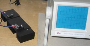
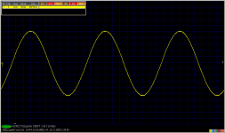

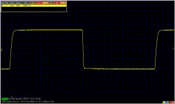
And several measurements of sine and squares, into 10R load.
Now I would like to apologize for a while from this thread - have fun with simple circuits! 😛
yes, return to the sources..!!
Hi Shaan, Pavel, guys.
As usual, I lost this interesting thread: I have bought all the necessary to build the power follower. I only lack time...
I was about to suggest that maybe the perceived difference in sound between Mosfet and Darlington was due, at least in part, to the monolytic Darlington and that we should consider a homemade one with "audio" bipolars. 😀 PMA is faster than me...
As this thread's audience is full of experts I would like to post a link to another power follower (and I do not pretend to hijack this thread, please) with another topology, that could be interesting, and in the mood to learn the basics of these circuit's function.
the Power Folllower
Dear Shaan, I will use a PowerReg type of capacitance multiplier supply:
Introducing the PowerReg - pink fish media
Good luck with your mod.
M
Willing to learn...
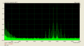
Now, it is a high time to mention that this kind of circuit needs very clean power supply. Let's explore the record of CCIF 13+14kHz distortion. We can see that it is not that bad for such a very simple circuit. Only low order harmonics to be seen - 2nd, 3rd, 4rd and 5th. Quite clean bottom background. BUT - a lot of intermodulation with 50Hz components. This is for the reason that the power supply used has only 5000uF filter cap. So, you would need 10-times more capacitance, or regulated PSU. As the current consumption does not change much, the regulated PSU, rated at some 5A, is the right choice.
Edit: I have not read your post as I was writing mine. You are of course right, maxlorenz, regarding power supply.
Edit: I have not read your post as I was writing mine. You are of course right, maxlorenz, regarding power supply.
Attachments
Last edited:
Hi Shaan, Pavel, guys.
As usual, I lost this interesting thread: I have bought all the necessary to build the power follower. I only lack time...
I was about to suggest that maybe the perceived difference in sound between Mosfet and Darlington was due, at least in part, to the monolytic Darlington and that we should consider a homemade one with "audio" bipolars. 😀 PMA is faster than me...
As this thread's audience is full of experts I would like to post a link to another power follower (and I do not pretend to hijack this thread, please) with another topology, that could be interesting, and in the mood to learn the basics of these circuit's function.
the Power Folllower
Dear Shaan, I will use a PowerReg type of capacitance multiplier supply:
Introducing the PowerReg - pink fish media
Good luck with your mod.
M
Willing to learn...
I do use two capacitance multiplier PSs for the original followers. It's from the Eliot Sound Products sound.westhost.com. They are quite clean and quiet.
Last edited:
- Status
- Not open for further replies.
- Home
- Amplifiers
- Solid State
- Pavel's MOSFET Follower - No Darlington Mod