I think you would just use one big one if you are going mono or two if you were going 2-channel.
I doubt that there would be a benefit for separate transformers for each module, since they are all processing the same audio. There could even be some weird interactions between multiple transformers but I'm not enough of an expert on electronics to answer that issue.
I doubt that there would be a benefit for separate transformers for each module, since they are all processing the same audio. There could even be some weird interactions between multiple transformers but I'm not enough of an expert on electronics to answer that issue.
Each modul, connected in parrallel, give 120 W/ 2 ohm. If you need ( theoretically ) 240 W/4 Ohm, you must to use two modules, which each will be connected in parallel, but one with " inphase ", second with " reversed phase " and load connect between both outputs. So for subwoofer you need two modules, for stereo operation four modules. I don't make kits, because in this amp are used commonly available devices, which you can to buy in every stores.
Upupa Epops said:So for subwoofer you need two modules, for stereo operation four modules.
Thanks for clearing that up, Pavel.
It's great that you included balanced inputs into the design, my new main amps (under construction) will be run balanced and sit next to my speakers ~30 feet(10m) of cable away from my preamp and sources.
Is it better to feed the PA03 inputs(as subwoofer amp) a signal from the preamp or the output terminals of my main amplifeirs? Linkwitz crossover and equalization boards for his Thor subwoofers will precede it.
I don't make kits, because in this amp are used commonly available devices, which you can to buy in every stores.
No $$$$ designer components? As Peranders posted seven months ago at the beginning of this thread "This can't be high-end. In fact, it must be rubbish." 😉
My bank account thanks you for using low priced parts.
To PMA : Typical peak current of each channel ( guaranted by manufacturer ) is 11,5 A , so in parallel mode it is 23 A. I mean, that for 240 W/ 4 Ohm it is enough 😉. To darkmoebius : Better is to drive it from preamp ( with crossover on the way, certainly ) than from PA - you get lower distortion and better SNR. And any expenive components ? Good results make mainly good circuit design and sophisticated PCB, not " for Titan's developed " devices, what is often declared on amateur pages and kit's magazines. 😉
Pavel,
we both are circuit designers, and as friends and colleagues I assume we should speak in a serious manner. The value 11.5Amps is output current limit for tON=10ms, typical. The guaranteed value is 7A (just look at the datasheet column at right side). 240W/4 Ohm means 7.74 Arms and 10.94Apeak, for purely resistive load. This will be increased for the complex load as speaker is. And the peak value you speak about is meant for output limitation in 10ms, not the continuous output current value.
There is another diagram in the datasheet, page 13. It shows 160W/4 Ohm in the parallel mode for 1% THD+N. Also, page 14 shows the safe operating area of the chipamp.
Frankly speaking, I would not recommend this 240W/4 Ohm, regarding the thermal load and safe area of the chip.
Regards,
Pavel
To PMA : Sure, you have certainly thruth, this circuit isn't " heavy duty tank " 😉 , 240 W of output power is rather theoretical value. For long time reliability is better in this case to use this circuit up to cca 200 W ( in parrallel / bridge configuration ), maybe little bit less ( I haven't long time experience ). 😎
Upupa Epops said:Thanks to PMA you can see measuring results of distortion LM 4780 in PA 03 module, measured by his multitone method. You can compare distortion of generator with distortion of complete amp. All is measured by output power 5 W / 8 Ohm and results are surprisely good. At first distortion of generator by 10 kHz :
5W into 8ohms... have you heard the expression "downhill
with a tail wind" 🙂
How about a stress test, say 50W into 4ohms.
Cheers,
Terry
To Terry : Here is measuring results by classical method on PC ( peak at 15625 hz is relict from TV and 19 kHz pilot signal from tuner ) - you see, home method 😉 . This is distortion at 6 kHz by 50 W / 4 Ohm ( " basic " harmonic isn't good filtered ). You can see still good results 😎 .
Attachments
moamps said:
100dB with 16bit measuring resolution?
100dB of resolution is 1 part in 10^5 . You have to do some range switching (or use a very good logarithmic amplifier) to get 100dB of resolution.
Take a look at manufacturer's spec sheets -- you very often have a case where there is a 50% probability that the smallest bit of an instrumentation ADC being correct. If you want to measure a microvolt referenced to 1 volt you need 20+1 bits of resolution. (So you make your work easier by changing the ref or amplifying the signal, all of which take a little time.)
Linear Tech has some good application notes on implementing very high resolution ADC's and DAC's -- these seem to me to be a lot more practical than Analog Devices or TI. Perhaps the crowd at LLTC has better editors, or more entertaining writers...
It is not that simple. For the FFT analysis, the noise floor is far lower, depends on number of samples in the FFT record, not only on A/D bit number. This is due to narrow band analysis and FFT algorithm.
Try to learn here:
http://www.analog.com/UploadedFiles/Associated_Docs/53331534274953968271515Section8.pdf
Try to learn here:
http://www.analog.com/UploadedFiles/Associated_Docs/53331534274953968271515Section8.pdf
jackinnj said:100dB of resolution is 1 part in 10^5 . You have to do some range switching (or use a very good logarithmic amplifier) to get 100dB of resolution.
Here is an another example of the > 96 dB problem. As you can see the noise floor is lower.
The measurement in post #229 was done with fundamental harmonic notch filter, and amplifier, this increases resolution by additional 20 dB.
OK!!
I think it is a good job on PCB. I'm waiting my boards to arrive here as the parts are all on desk. Thanks for your offer of this design (saved a lot of my time on PCBCAD).
Regards.
Euclides.
🙄
I think it is a good job on PCB. I'm waiting my boards to arrive here as the parts are all on desk. Thanks for your offer of this design (saved a lot of my time on PCBCAD).
Regards.
Euclides.
🙄
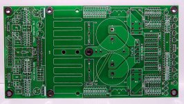
I have one of those boards and they are excellent, one of the best I have ever seen.Upupa Epops said:This is photo of PCB. Do you like it ?
 nod:
nod:Boards still availaible ?
Hi P-A, ....Pavel ,
Are there still boards availlaible ? i have 4780s from National and want to build one of these for my son's birthday.
To get him to know good engineering...
...Another Carlos 😎
Hi P-A, ....Pavel ,
Are there still boards availlaible ? i have 4780s from National and want to build one of these for my son's birthday.
To get him to know good engineering...
...Another Carlos 😎
I'm sorry, but I have any PCB's at this moment. I can to let made them, but it should be minimal ten customers ( ten pieces is minimal order in factory ).
- Home
- Amplifiers
- Chip Amps
- Pavel Dudek's (Upupa Epops) LM4780 amp