fast relay action
a small modification.
Add a resistor (R5) to the vertical link above C1.
Move the +ve end of D1 to the +ve of C1.
Adjust R5 to set the operating current of the closed relay.
This gives a very fast snap action to the closing of the relay and allows a low voltage relay to be fed from a (much) higher voltage supply.
If R5 is chosen to keep the relay just closed after firing on the lowest worst case supply voltage, you will find that the relay drops out more quickly than feeding it with it's nominal voltage.
Hi Andrew,
The delay board operates at rail voltage (56VDC) and feeds the softstart board:

On the soft start is the series resistor (10 in parallel) and zener to cut the supply down to 12VDC for the relays. I calculated the current required by measuring the coils resistance.
I have it running now and it's working well. Very nice ~1 second delay before the relays close. If I had my time back, I'd have combined the two - softstart and delay timer on one board. Next time.
The delay board operates at rail voltage (56VDC) and feeds the softstart board:
On the soft start is the series resistor (10 in parallel) and zener to cut the supply down to 12VDC for the relays. I calculated the current required by measuring the coils resistance.
I have it running now and it's working well. Very nice ~1 second delay before the relays close. If I had my time back, I'd have combined the two - softstart and delay timer on one board. Next time.
the Vcc out feeds the relay coil, doesn't it?
If so then your 11 5k6 resistors are the R5 I added. But it must be in that new location I suggested.
You can then delete the Zener. Or keep it if you require faster relay drop out. But it must be reversed and a series diode added to prevent it passing when the relay coil is energised.
You may find that you can increase R5 from 5k6/11, a couple or more of e12 values. That is because it's the charge across C1 that fires the relay. R5 then keeps the relay closed at maybe half nominal relay current.
Have you noticed that Vbe of Q2 rises to ~12V as the timing capacitor charges? I think you should reduce the 150k to 47k and find the new capacitor value for your 1second delay. Your circuit survives because the excessive base current of Q1 pulls down the base voltage after passing that 470k.
Here is what I have:

But on 2 boards. The timer is working at full rail voltage and the divider cut that down to 12 volts. I don't see a problem...relay drop out is not an issue, neither is pickup speed - the thermistor is carrying the bulk of the current at that point.
But on 2 boards. The timer is working at full rail voltage and the divider cut that down to 12 volts. I don't see a problem...relay drop out is not an issue, neither is pickup speed - the thermistor is carrying the bulk of the current at that point.
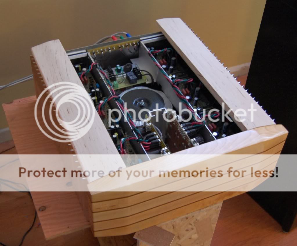
Wired, installed and working:

Don't look at my "fuse" (green wire) 😀
Temporary (for testing) until I get an 8 amp 5mm x 20mm.
I'm done on the inside!
Now to finish the outside.
The front is done but I don't like it anymore...sick of looking at it laying around. It has a knot in a very conspicuous place and that is really ringing my ugly bell...so...I'm thinking about painting it (the front). The computer case that this front was made to match is a dark candy apple red - what colour could I paint this? Not black, I'm tired of black. Maybe a darkish electric blue (by the same painting process as the computer case, with a black undercoat and layers of blue candy...Mmmm).
Sounding good and being good are not enough - it has to look good too.
MJL21193 said:Don't look at my "fuse" (green wire) 😀
LOL! That cracked me up. Not only is there a wire in the fuse holder, but the board has a big label there that says FUSE 🙂.
andy_c said:
LOL! That cracked me up. Not only is there a wire in the fuse holder, but the board has a big label there that says FUSE 🙂.
Glad you found that amusing... a touch of ridiculous irony. My normal method is to "fix" the blown fuse with a strand of thin wire soldered across but I'm all out of 5 x 20 fuses. Need to order more.
I sanded the front; sanded the aluminum touch strips down flush with the surface of the wood. Sanded it to receive a coating of polyester resin. I mixed up 2 cups of that and poured it on. It's thick and went on pretty smooth and has cured now (I'm dizzy from the fumes).
Next step will be to give it a few coats of flat black - the base for the electric blue candy. Exciting stuff!
MJL21193 said:Board copper bottom in high quality .pdf for those (like me) who can make there own boards:
And for those who want to make their boards at a factory to be with a neat silkscreen and solder mask ... or are just too lazy to make them theirselves .... any gerber files? 😀
Hi kalmara,
I'll get the Gerbers posted soon. A word of warning: the drill file holes are not standard. I'm not sure how a board house would handle that - might be worth including a note with the board order.
I'll get the Gerbers posted soon. A word of warning: the drill file holes are not standard. I'm not sure how a board house would handle that - might be worth including a note with the board order.
Originally posted by MJL21193
Thanks duda,
Sorry for the slow response - I've been away.
The link I can't find but I did save the pdf. Send me an email and I'll forward it to you.
It is I again John, pestering about the application note. 😀
I will send you another email.
No rush, just curious to see the article.
Thanks!

dudaindc said:
No rush, just curious to see the article.
Sent...🙂
Some news:
The 6 channel amp is fully functional and being used every day to drive my active three-ways (here).
I haven't finished the chassis; although the major metal work is done, I still need to d the "cosmetics" - the front plate and close in the top. I had a front plate done (shown earlier) from fir but I didn't really like the way that looked. I painted it but that didn't appeal to me either - it wasn't quite the look I wanted. I want something hefty - solid looking, massive. I went back to the workshop and came up with this:

Solid maple with thin strips of black walnut between. Shown here after receiving a coat of clear urethane. Not finished yet but a sneak-peak.
I have several things to do today but my attention keeps getting drawn back to this project...😀
Now that the front is finished, I can work on the top. My original idea was to use 1/2" aluminum tubes (which I have a pile of) to do the top but I have reconsidered. Sticking with the wood theme, I just made these:
The idea is to make slats to go across these to fill in the middle. Space the slats 1/4" for ventilation (and to peek inside).
I have also decided to paint the heatsinks flat black, so I'll do that when I dismantle it before I install the front.
Originally posted by MJL21193
Sent...🙂
Thanks John!
Originally posted by MJL21193
...
I went back to the workshop and came up with this:
Solid maple with thin strips of black walnut between. Shown here after receiving a coat of clear urethane. Not finished yet but a sneak-peak.
WOW!

dudaindc said:
WOW!
Thanks!
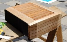
I painted the heatsinks black and I think it looks better. I attached the front and finished building the top.
I didn't have enough black walnut to do the slats for the top, so I used a particularly dark piece of cedar I had, thinking the it would be close enough to the colour - wrong! I don't like it so I've decided to paint the slats black, just the slats, not the maple side pieces.
Getting to the end of this project. a long time (for me) in the works.
Attachments
It was a good choice IMO, the black looks good. I have most of it done:


Front is attached, feet are on front and back and the top is finished (just one more coat of clear urethane on the maple left to do). Ready to put back in service.
Front is attached, feet are on front and back and the top is finished (just one more coat of clear urethane on the maple left to do). Ready to put back in service.
Member
Joined 2009
Paid Member
Bigun said:
Thanks!
🙂
Bigun said:I want one of these, give me one[/B]
No problem, I'll put one together tomorrow morning.

dudaindc said:Awesome!!!
Thanks Duda,
It's rewarding when it all comes together and it turns out even better than I expected. It all came up aces here at the finish line.
😎
- Status
- Not open for further replies.
- Home
- Amplifiers
- Solid State
- Patchwork Reloaded: Circuit Optimization and Board Layout.