Hmm, we will need to pray for someone who knows the answer to chime in. (where's Glen?) 🙂
They are from the original Krell amp. I thought to remove them but THD went up and stability went down. Who am I to argue? I left them in, but reduced the value from 470uF to 220uF.
Musical? 🙂
They are from the original Krell amp. I thought to remove them but THD went up and stability went down. Who am I to argue? I left them in, but reduced the value from 470uF to 220uF.
Musical? 🙂
Now that I looked at it real hard maybe a couple of Zeners C5/C6, C2/3 are hard bridged??
😕
R27 maybe bigger, 100R, better current gain , less heat.
😕
R27 maybe bigger, 100R, better current gain , less heat.
c7 & c8 bypass the emitter resistors. installing these caps radically raises the gain of the vas stages. when you put these in, your open loop gain went up, so you had a lot more nfb to drive thd lower.
... but you don't get something for nothing - your thd will start to climb back up as the freq drops. not to mention what could happen during clipping, etc.
are you saying the ksa-50 had these caps? i don't remember them, but it's been a while since i looked at an old krell schematic.
mlloyd1
(still having lots of fun looking your shoulder 😉 )
mlloyd1 said:c7 & c8 bypass the emitter resistors. installing these caps radically raises the gain of the vas stages.
See, I was too modest to explain, so I let someone else take all the credit...

Thanks mlloyd.

The KSA50 schematic I have shows it:
Attachments
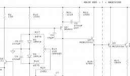
ostripper said:Now that I looked at it real hard maybe a couple of Zeners C5/C6, C2/3 are hard bridged??
😕
R27 maybe bigger, 100R, better current gain , less heat.
Zeners are a bad word, OS. We don' need no stinkin' Zeners!
R27 is not the final value. We are witnessing a work in progress, and I am trying different things, following different avenues, all toward the best performance.
Anyway, I'm threadjacking my own thread but that's ok. I need to get back in the saddle and complete the Patchwork project. Some changes to the schematic that I've come up with and I want to work on a good board layout, one that will shine and strike fear and awe in the hearts of all that gaze upon it... 😀
Seriously, in another thread I exposed my current layout for critical comment and it wasn't pretty. 🙁 Eva pointed out a few areas of improvement that I will be working on.
MJL21193 said:
I have thrown out the design above and developed a new one. I have been working on this one (adapted from the KSA50) for about a year, off and on. Obviously, I didn't have these outputs in mind originally, but things change.
It looks good in simulation with low THD and very good stability.
I have put that design back on the shelf in favour of roender's RMI amp. It looks really good in simulation. Not ultra-low THD, but very stable and well behaved. Slew rate looks very high. It will be an interesting project.
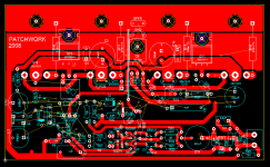
I have spent some time tearing apart the Patchwork board layout and reworking it (again!). I'm making some progress. Big changes so far are to move the decoupling/ bypass caps for the output stage near the middle, along with the rail entry connectors. This makes good sense as it frees up real estate at the ends of the board.
I want to keep the board the same size and by making the changes I have so far, it gives me more space to organize the front end.
Attachments


Over 100 views and no comments? Is it that bad?? 🙂
I still have a change to do - add the opposed diodes in parallel to R25.
Here's a comment, What do you use as an editor??? eagle?
Also, with all the extra real estate go for bigger decoupling caps
(220uF) I,ve been adding fake ripple in sim PS's (AC 56 4 120)
to see a better simulation of the real world, PSRR, etc..
OS
Also, with all the extra real estate go for bigger decoupling caps
(220uF) I,ve been adding fake ripple in sim PS's (AC 56 4 120)
to see a better simulation of the real world, PSRR, etc..
OS
ostripper said:Here's a comment, What do you use as an editor??? eagle?
Also, with all the extra real estate go for bigger decoupling caps
(220uF) I,ve been adding fake ripple in sim PS's (AC 56 4 120)
to see a better simulation of the real world, PSRR, etc..
OS
Ultiboard. Eagle kooks ok, and I've tried using it lately, but I'm already well acquainted with Ultiboard.
I have good, low ESR caps with the same pin spacing for 220uF as 100uF so it doesn't require any layout change. Besides, I'm not having any PS noise or hum to deal with. When I connect to the DCX2496, that's a different story. That has a bit of noise that I may try to fix. Other sources are dead silent.
Oh, no.. 100uf will be fine , especially with your cascoded
diff. ,but when you are running 6 amps off the same PS
ANYTHING you can do to lower PSRR is a good thing.
On the 5 channel Japanese HT amps, I notice they don't
even have midsized decouplers (100-220uF). All they
do is cram the main filter caps in the middle,run a solid copper
bus to all OP devices,just decouple the driver chips (LM-XX,
STK-XX) w/.22uF's and rely on the good PSRR of the IC's.
But why make NFB and the LTP work harder than they have to??
I will try utiliboard as I like the way you can make custom
layouts with it ,since you use it, could you give me a few pointers
on it??
Thanks, OS
ostripper said:,since you use it, could you give me a few pointers
on it??
Me? Give pointers? I'm in need of those myself! 🙂
The drawback is that it interfaces with Multisim, and would probably be most efficient that way. There's isn't anything wrong with Multisim, it's just that if you have already figured out how to do things in Eagle, you have another learning challenge ahead. Eagle (from my little experience with it) is much different from MS/UB. Which one is better? I'm biased.
The 6 amps will be running off 2 power supplies that share a common transformer. Each PS has 23500uF per rail smoothing caps. Also, the end use for this 6 channel amp is a pair of 3-way speakers. The mid and treble combined will come close to the power usage of the bass. I haven't had a problem running with it half done (three channels into one speaker) and I don't anticipate any problems when I eventually finish the other 3.
Hi John
I have not checked the small signal layout in detail, but I think that there is little room for improvement in the power layout, unless you go for a larger or a double sided PCB or a daughter board. In any case, it's better than average, it lacks most of the usual mistakes 😉
I would probably do some changes to the ground track in an attempt to improve PSRR a little.
Eva said:
I would probably do some changes to the ground track in an attempt to improve PSRR a little.
Thank you very much Eva. 🙂
I tried to put into action all of the pointers you gave in that other thread. It will be nice to have this knowledge to draw upon for future layouts. Starting off in the right direction is always the best way.
Do you see a problem with the length of the feedback trace and how it routes between the P- and the ground?
Can I ask what changes could be made to the ground that would improve PSRR? I'm interested in any advice, barring a top layer, as these improvements are all free.
Decoupling capacitors will tend to carry chopped halves of speaker current at high frequencies. These currents will tend to produce voltage drops across the ground system. If you connect the capacitors to ground in a symmetrical way and take ground references from the middle point, the voltage drop across the ground track will become the sum of both halves with equal weight so it will not contain extra harmonics. Asymmetrical connection results in more voltage drop from one of the halves and harmonics.
Eva said:Decoupling capacitors will tend to carry chopped halves of speaker current at high frequencies. These currents will tend to produce voltage drops across the ground system. If you connect the capacitors to ground in a symmetrical way and take ground references from the middle point, the voltage drop across the ground track will become the sum of both halves with equal weight so it will not contain extra harmonics. Asymmetrical connection results in more voltage drop from one of the halves and harmonics.
Thanks again,
This makes sense. You are referring to the larger ones, on the output stage I hope. Harder to get that kind of thing happening on the ones for the front end.
I'll do it and post back a picture. I have made a few other small changes.
Eva said:
Isn't the RC network from output to ground missing? It should be in the amplifier PCB near the power stuff.
Ah, the Zobel. I left it off the first layout, thinking I would put it at the output terminals of the amp. It is added in here:
An externally hosted image should be here but it was not working when we last tested it.
Better?

John,
I think the design bug has bitten you big time. Once you have finished this amp you will most probably start the next one and the next.... I think you should start a www.patchwork.com web-site.
I think the design bug has bitten you big time. Once you have finished this amp you will most probably start the next one and the next.... I think you should start a www.patchwork.com web-site.
- Status
- Not open for further replies.
- Home
- Amplifiers
- Solid State
- Patchwork Reloaded: Circuit Optimization and Board Layout.