Hi Nico,
Already working on the next ones 😱
I'm just taking this project to a worthwhile conclusion. I don't like to leave things half done. The circuit (after much tinkering) is as good as it can be for this type of amp. Finalizing the board layout and honing my skills in that area will be put to good use on future designs.
Patchwork.com - has a nice ring to it, doesn't it? 🙂 - lots of hits for quilts, I'm sure.
Wouldn't it figure - now that I have the board layout complete, I'd start screwing with the circuit again?
I have been experimenting with 2-pole compensation. In the simulation I have been trying different values for the before/after caps. I also thought to try to change the centre point from a pick off the rail to a few different place to see what gave the best stability.
First I went to ground - no improvement, in fact worse. Then I though to try places at random (remember, I don't know what I'm doing 😱
I tried the output from the VAS - quite a bit better than the rail
I tried the output from the LTP - better still.
Played around a bit more with the values and came up with what's below. Is this a good idea?
Attachments
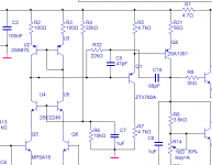
Close ,but no cigar.. you are shunting one of your poles.(C5)
Ratio is important ,too (C5/18 = 1/2 = 47p/100p). center of
caps (R32) should be "set" to somewhere other than
the signal path (V+).
The second question is , why is it better?? More nfb over
a band of audio (peak) resulting in lower THD for that band.
But it has a downside ,VAS is delinearized if you dont get
R32 just right (6.8k?).
I played around with it but I figured silver micas were too expensive
($1.20)as I can buy 10 transistors for the same $.
It can make for a more stable amp with less HF distortion. So,
play around with it..
good looking mod...
PS.. a little 10-33pf SM cap right in the NFB loop produces that
same peak without "freaking" out Cdom..
OS
Ratio is important ,too (C5/18 = 1/2 = 47p/100p). center of
caps (R32) should be "set" to somewhere other than
the signal path (V+).
The second question is , why is it better?? More nfb over
a band of audio (peak) resulting in lower THD for that band.
But it has a downside ,VAS is delinearized if you dont get
R32 just right (6.8k?).
I played around with it but I figured silver micas were too expensive
($1.20)as I can buy 10 transistors for the same $.
It can make for a more stable amp with less HF distortion. So,
play around with it..
tack some smd's on bottom of board,slice a trace or 2 , a neat andWouldn't it figure - now that I have the board layout complete, I'd start screwing with the circuit again?
good looking mod...
PS.. a little 10-33pf SM cap right in the NFB loop produces that
same peak without "freaking" out Cdom..
OS
ostripper said:Close ,but no cigar..
Hi OS,
The point wasn't the use of 2 pole, but where I picked the centre from. The scheme above gave the best stability and I was looking for a reason why the output from the LTP would be better than the rail or ground. I didn't even consider THD for this, but did check after and it is unchanged a 1k but slightly lower at 20k.
As to the values, I used the lowest possible to get the best results ( 68p same results as 100p)
ostripper said:
tack some smd's on bottom of board,slice a trace or 2 , a neat and
good looking mod...
PS.. a little 10-33pf SM cap right in the NFB loop produces that
same peak without "freaking" out Cdom..
OS
I'll try it out on one of the older modules and see how it works. If it improves the overshoot, I'll put it in the new layout. Not that big of a deal.
I had trouble with the cap in parallel with the feedback R before in the original incarnation of this amp. I haven't tried it with this one, so I may do that.
Remember, it's not instability that I'm trying to solve but the overshoot.
maybe too much OLG, when I started using the 1381's with my first amp I got 70db (versus 53db w/mje350) this gave me overshoot in sim. I later degen'ed my LTP to do 60db.Remember, it's not instability that I'm trying to solve but the overshoot
your Vas is EF'ed, must have overkill gain but that would depend
on the grade of 1381's you have (F=300 E=150 c=40-80Hfe)
I ordered 20each of the "F's" as your model seems to reflect the
higher gain group.
OS
ostripper said:
your Vas is EF'ed, must have overkill gain but that would depend
on the grade of 1381's you have (F=300 E=150 c=40-80Hfe)
I ordered 20each of the "F's" as your model seems to reflect the
higher gain group.
OS
Yeah, I tried it without the EF - no difference. I tried a higher gain (the Zetex above) for the EF and actually saw an improvement. Could be worth doing.
I need to muck around with the actual circuit, change some things to see how it looks on a real scope.
The F version of both is what I have.
Endless tinkering and I have changed up again. Armed with better understanding (it grows daily 🙂 ) I have made some improvements:

I have ditched the EF on the VAS - various reasons.
I added an emitter resistor to the VAS and lowered it's working current.
I increased the cascode voltage in the input by changing R6 to 22k.
Otherwise, everything else is the same. I haven't tried these changes on the actual amp yet, but I can't see any problems.
I'm also thinking about lowering the gain to limit this to 100watts output at max input (1.2Vrms). This will allow the amp to use the same power supply (or lower if required), but leave some headroom for clipping. I haven't included the clamp diodes for this reason.
I just update the pic above to include a change to the CM on the LTP. It has an impact on THD, mostly at higher output power.
I changed the gain also, as mentioned above.
THD is very low. I won't bother to show the plots but it's certainly low enough. Better this time is the 3rd and higher harmonics are much lower than the 2nd.
AC analysis:

Loop gain:

PSRR:

I changed the gain also, as mentioned above.
THD is very low. I won't bother to show the plots but it's certainly low enough. Better this time is the 3rd and higher harmonics are much lower than the 2nd.
AC analysis:
Loop gain:
PSRR:
MJL21193 said:Endless tinkering and I have changed up again. Armed with better understanding (it grows daily 🙂 ) I have made some improvements:
Hi John, should C12 not be connected to the output, or do you have a reason for the configuration.
Nico
A final remark, I am not sure if your CCS is really up to task, it will vary with varying supply voltage, the diode is referenced to a resistor that will drop voltage depending on the supply.
I would remove the 470 Ohm resistor and use another diode or maybe two diodes.
I could interpenetrate it wrong and you intended something else with this circuit.
Nico
I would remove the 470 Ohm resistor and use another diode or maybe two diodes.
I could interpenetrate it wrong and you intended something else with this circuit.
Nico
Nico Ras said:
Hi John, should C12 not be connected to the output, or do you have a reason for the configuration.
Nico
Hi Nico,
Connecting the bootstrap cap to the emitter of the driver was recommended by jcx earlier in this thread. It seems to be beneficial.
Nico Ras said:A final remark, I am not sure if your CCS is really up to task, it will vary with varying supply voltage,
I was confused too (as well as others).
It is, in fact, a current mirror and not a CCS. It has a huge impact on THD at high output, at least in this circuit. See some talk about it starting here.
By nico - A final remark, I am not sure if your CCS is really up to task, it will vary with varying supply voltage
I think he meant put a proper one in like mine(led/diodes/tranny
cap) see my Psrr on the FA3 ,almost -90 at 120hz . Cheap
fix..🙂
edit (not the top Cm , at the bottom under the LTP Re's)
if you keep the Cm, your estimated PSRR should be - 93-96Db
at 120 Hz with a proper CCS at bottom.
OS
ostripper said:
I think he meant put a proper one in like mine(led/diodes/tranny
cap) see my Psrr on the FA3
Hi OS,
No, he was referring to the current mirror - that's clear.
My PSRR is excellent for this amp and I have no intention of replacing my simple single resistor with a "proper" CCS.
🙂
danielwritesbac said:Have you heard it sing?
EDIT: I mean, have you used it for music yet?
Indubitably, my dear Dan. 🙂
Look a little further back in this thread and you will see the 6 channel monster.
Oh, I was referring to the recent modifications. If they were't recent, perhaps I misunderstood. Or maybe you're a very "quick draw" with the soldering iron. 😉
Not the latest mods, but it is basically the same performance, just with a few less parts and possibly better stability.
I will see if I can motivate my lazy a$$ tomorrow and make the changes on an existing board.
I will see if I can motivate my lazy a$$ tomorrow and make the changes on an existing board.
On such a comparison, if its with the ear, see if there's different answers to these questions:
Does the piano/cello have the same clarity at the baritone as it does at a higher pitch?
EDIT: Any larger string instrument will do.
Do the reverb echos from a studio-reverbed recording merely decrease in loudness or do they taper off farther and farther away?
EDIT: Farther away is more involving and would usually have been the choice of the studio. Check several recordings.
Does the soundfield projection size decrease or increase in size when played louder?
EDIT: When a soundfield is amplified, it should get larger, else there is a blare if it "only" gets louder.
Of course both amplifiers should do well, but the interesting part (for me) is when there's a difference and then spotting the cause of it.
- Status
- Not open for further replies.
- Home
- Amplifiers
- Solid State
- Patchwork Reloaded: Circuit Optimization and Board Layout.