megajocke said:Are they Toshibas or are they another brand?
The onsemi MJL2119x are well known for their robustness 😀 I see arrownac.com has NJW21193 & NJW21194 for $1.87, they are the same chip but in TO3-P case instead of TO264. I don't know about their shipping charges to Canada but I'm sure it's cheaper than shipping to here, which was a bit expensive
They are the Fairchilds. The 21193/94 are brutally tough, but I wanted to try something a bit faster here, therefore I went with the junk...er, I mean 2SA1943/5200 combo.
For DC protection I think I'll just use a crowbar, mounted inside the speakers. One for each driver, as this is actively driven. I know, not the very best solution but fast and easy plus effective.
Judging by how fast the rail fuses blow on the modules, I might save an output or 2 in the event of a fault.
Two of the three installed modules are working fine with the higher Cdom and the Zobels. The third is going to need some diagnostics to try and find what else I burned with the solder bridge that I accidentally made replacing the Miller cap. Vas and EF have been replaced so far, but it's still not working correctly. Not enough excitement, but I need some more of my patented stupid mistakes.😡
"therefore I went with the junk...er, I mean 2SA1943/5200 combo."
Sorry to bother but I have a Primare 5 channel amp with this combo and one of the 2sa1943 transistors shorted.
Do I have to replace it with the Toshiba or can I use another combo?
Thanks Steve
Sorry to bother but I have a Primare 5 channel amp with this combo and one of the 2sa1943 transistors shorted.
Do I have to replace it with the Toshiba or can I use another combo?
Thanks Steve
Fairchild and ST produce those devices too, but there might be some differences. The price difference isn't big, the Toshibas are cheap from for example digikey.
MJL: If you feel they are not tough enough they make fine driver transistors for big output stages 🙂
MJL: If you feel they are not tough enough they make fine driver transistors for big output stages 🙂
Hi,serosmaness said:
Do I have to replace it with the Toshiba or can I use another combo?
Do you mean another type, like maybe the MJL21193/94 pair? Should be ok but a look at the schematic would be better.
megajocke said:
MJL: If you feel they are not tough enough they make fine driver transistors for big output stages 🙂
Yes, I am spoiled by heartier parts. They would make pretty good drivers, wouldn't they? Running full classA or high bias CFP. Plans are forming in my head.😱
I looked at the MJL4281A/4302A at Digikey. They have gone up in price $2 due to our sagging dollar. I should have stocked up a couple months ago.
I have tried the Onsemi combo mjl3281a/mjl1302a as I have some already, and the Onsemi website said that they are compatible.
Any thoughts?
Thanks Steve
Any thoughts?
Thanks Steve
That should work just fine 😀 Those parts are probably more robust too. I'd check that the amp is still stable when doing a substitution.
MJL: If you want to play with the Thermaltrak NJL3281D and NJL1302D the non-lead-free versions (IMO a good thing) are very cheap at arrownac.com right now. 😱
MJL: If you want to play with the Thermaltrak NJL3281D and NJL1302D the non-lead-free versions (IMO a good thing) are very cheap at arrownac.com right now. 😱
As Mega said, stability needs to be checked. These are very good outputs.serosmaness said:
Any thoughts?
Thanks Steve

megajocke said:That should work just fine 😀 Those parts are probably more robust too. I'd check that the amp is still stable when doing a substitution.
MJL: If you want to play with the Thermaltrak NJL3281D and NJL1302D the non-lead-free versions (IMO a good thing) are very cheap at arrownac.com right now. 😱
I see that they are about $1.50 less than the MJL4281A/4302A on Digikey. Digikey is much more convenient (fast shipping) and by the time I get nailed with duty and the UPS brokerage fee at the border when buying from Arrow, it winds up cheaper maybe to get them from Digikey.
I could have fun playing with these. You corrupt me to start a new design Mega! 😱
I have taken the big step and connected the finished half of this to my speaker for a listen. It took a while to get the DCX up and running and I'm using the PC interface (this makes it SO convenient).
Welcome to my nightmare:

Three channels, three drivers - sound is great! This is playing with one of my active 3-way workshop speakers as the left channel.
It is very impressive so far.
They are trying to get rid of them for $0.57 and $0.78, that is - the Thermaltrak NJL1302d and NJL3281d. I couldn't resist buying some - I guess most manufacturers also want to be able to sell to EU and can't use them in products because their lead-free solder baths will get contaminated... :O
I bough, errm, a few of them. I guess I will have to only design amps which use these from now on or make a kit and sell or something...
I bough, errm, a few of them. I guess I will have to only design amps which use these from now on or make a kit and sell or something...
How many is a few? 😀
I just ordered 25 of each from Arrow. I figure I'll still be saving a few bucks and this will be a nice addition to the toy box.
I just ordered 25 of each from Arrow. I figure I'll still be saving a few bucks and this will be a nice addition to the toy box.
I bought 125 of each 😀 As the shipping was pretty expensive it wouldn't have been worth buying just a few 🙂
Looks like they have run out of the NPN:s now, but there are about 1500 left of the PNP:s.
I just got a 500VA 2x50V transformer cheap. Good enough for 1/3 average power in 8 ohms or barely 1/8 power in 4 ohms so maybe a class G amp with this for the upper rails and 2x24V or 2x30V transformer for low rails 😀
your 500VA, 50+50Vac should give around +-75Vdc to +-80Vdc.
This is good enough for ~220W into 8r0 and ~400W into 4r0.
This transformer could run a single 4ohm load or two channels with 8ohm loading.
This is good enough for ~220W into 8r0 and ~400W into 4r0.
This transformer could run a single 4ohm load or two channels with 8ohm loading.
Yes - that's about what I figured. With class AB it will be enough for 2x8 ohms playing music, at 4 ohms probably not unless average power is low like for mids or tweeter in an active speaker.
That's why I'm thinking of class G. Will give much lower dissipation and power consumption, especially for dynamic material and/or moderate levels. I'd need about the same number of output devices like this, 2 pairs of outputs and 2 pairs of lifters seems workable at +-70V high and +-30V low rails.
That's why I'm thinking of class G. Will give much lower dissipation and power consumption, especially for dynamic material and/or moderate levels. I'd need about the same number of output devices like this, 2 pairs of outputs and 2 pairs of lifters seems workable at +-70V high and +-30V low rails.
megajocke said:I bought 125 of each 😀 As the shipping was pretty expensive it wouldn't have been worth buying just a few 🙂
Looks like they have run out of the NPN:s now, but there are about 1500 left of the PNP:s.
I just got a 500VA 2x50V transformer cheap. Good enough for 1/3 average power in 8 ohms or barely 1/8 power in 4 ohms so maybe a class G amp with this for the upper rails and 2x24V or 2x30V transformer for low rails 😀
Nice grab Mega. 🙂
I am kicking myself now for not ordering more than the 50 as I didn't get nailed for duty at the border. If I had my time back, I would and doubled that. Oh well.
I received both of my goodies yesterday - new outputs and new toroids:

That's a 52-0-52 550VA, a 29-0-29 625VA and an 18-0-18 100VA. Ready for a few more projects!
I have a tentative scheme for the thermal tracks. Still need to iron out a few details.
Attachments
Looks like you'll have way too much bias voltage like that, if you change to triple-EF output you could probably use the same vbe multiplier circuit as in the leach amp (4 diodes). The 2 diodes that are left could be used for something fun, like overtemperature protection if one wants 😛. That circuit you have now with CFP drivers could maybe work with two diodes and a whole vbe multiplier in series with them or three diodes with a pot in series, maybe a 1n4148 across the pot could be useful...
A good thing with the CFP is that driver temperature won't disturb the bias almost anything at all. I'm planning to try CFP predriver/driver with these for that reason.
But didn't you have problems earlier in the big amp with CFP predriver-driver? I belive you can probably get it working if you use base resistors on outputs, but I probably wouldn't try without at least some means to add them easily.
Those VAS devices look nice, I'll save the part number - those look very useful as VAS/predrivers 🙂
Hi Mega,
Yes, don't pay attention to the 6 diodes - I have some difficulty with Multisim to get an accurate voltage drop across diodes.
I took the time to measure the actual drop on these diodes at my VAS current (8mA) and it is .56V at 25*C.
I think that I can use 4 on their own to give ~2.24V bias. This will put my idle current in the 120-130mA range.
I like your idea of using the other 2 as part of an overheat protection circuit. Or perhaps just to activate a cooling fan.
I had problems with the CFP arrangement before but I think that was due to the physical size of the output stage and my choice of devices. I used it on my very first DIY amp project (Rod Elliot's P68) and didn't have any stability issues.
I'm willing to take another crack at it. Maybe we could collaborate, since we both are shooting for about the same thing. 😱
I could mail you a couple of the 2SA1381's to play with if you like. Least I could do for the help you've given me. Let me know.
Hi, MJ . I see you have some (alot) of those T-TRacks.
Over in the t-trak thread doug self and others did the usual thing and fretted over how to implement Vbias with them.
Many crazy methods were discussed but in the end prof. leach's
multiplier with variable coefficient was decided upon
.
OS
Over in the t-trak thread doug self
and others did the usual thing and fretted over how to implement Vbias with them.Many crazy methods were discussed but in the end prof. leach's
multiplier with variable coefficient was decided upon
.OS
Hi OS,
I think that adding a pot across one of the bias diodes will give me enough adjustment leeway.
Putting the idle current per device in the 100-200mA range will give the best (simulated) results.
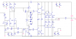
I have been playing around and discovered a couple of different things, one of which can be applied to the Patchwork amp. First, the "bootstrap" resistor on the frontend appears to be too high at 450K. I'm seeing much better results with a lower value. Second, the CFP drivers seem to be more stable when the first device is high speed. This plays out with a few different models in this location, but I can't count that as conclusive.
Here's what I have thus far. All six of the bias diodes will be series in, but I'll use links to short one or two if I don't need them on the prototype board (somewhere in the future). I've included 5 here for simulation.
Running on ~70 volt rails, I may add another output pair. Input sensitivity needs to be adjusted for the higher rails.
I think that adding a pot across one of the bias diodes will give me enough adjustment leeway.
Putting the idle current per device in the 100-200mA range will give the best (simulated) results.
I have been playing around and discovered a couple of different things, one of which can be applied to the Patchwork amp. First, the "bootstrap" resistor on the frontend appears to be too high at 450K. I'm seeing much better results with a lower value. Second, the CFP drivers seem to be more stable when the first device is high speed. This plays out with a few different models in this location, but I can't count that as conclusive.
Here's what I have thus far. All six of the bias diodes will be series in, but I'll use links to short one or two if I don't need them on the prototype board (somewhere in the future). I've included 5 here for simulation.
Running on ~70 volt rails, I may add another output pair. Input sensitivity needs to be adjusted for the higher rails.
Attachments
I see you are on it , MJL. The vbias circuit is the only one
that really needs a "real world" setting. When I built frugal 1
I found that my sims and calculations were somewhat off/
wrong (and the self amp handbook also)Different OP devices
have different thermal coefficients, as do different heatsink/ops
combinations, and where you put the Vbias (on the HS or
directly on the device)It has a lot to do with timing.
I debated this on the t-trak thread (over compensation
was the term), The best way If I had only T-traks to build
with would be to buffer the internal diodes with a typical
BD139 Vbias circuit (AKA prof leach) because the response
of the internal diodes are way too fast and the current from
your VAS with also pass through them, with rapid changes in
bias current.
hook 4 diodes between A/B ,leave r27 /P1, maybe change
R25 to a trimmer to adjust the coefficient.Make C big ,as
the on-die diodes are real (too)quick.
I experienced this on my amp with VBe right on the device!!
For my NJL0281's (similar to T-traks) this ratio..
r18+vr2= 875R / r17=2.7K - the roughly 1/3 ratio kept my OP's at 50ma(I get Xover distortion at under 35ma)
startup, 60ma normal use, and climbing to 70ma then compensating (backing off)at 40C+.
this is something you are going to have to play with as
the real world is much harder to sim.
OS
that really needs a "real world" setting. When I built frugal 1
I found that my sims and calculations were somewhat off/
wrong (and the self amp handbook also)Different OP devices
have different thermal coefficients, as do different heatsink/ops
combinations, and where you put the Vbias (on the HS or
directly on the device)It has a lot to do with timing.
I debated this on the t-trak thread (over compensation
was the term), The best way If I had only T-traks to build
with would be to buffer the internal diodes with a typical
BD139 Vbias circuit (AKA prof leach) because the response
of the internal diodes are way too fast and the current from
your VAS with also pass through them, with rapid changes in
bias current.
An externally hosted image should be here but it was not working when we last tested it.
hook 4 diodes between A/B ,leave r27 /P1, maybe change
R25 to a trimmer to adjust the coefficient.Make C big ,as
the on-die diodes are real (too)quick.
I experienced this on my amp with VBe right on the device!!
For my NJL0281's (similar to T-traks) this ratio..
An externally hosted image should be here but it was not working when we last tested it.
r18+vr2= 875R / r17=2.7K - the roughly 1/3 ratio kept my OP's at 50ma(I get Xover distortion at under 35ma)
startup, 60ma normal use, and climbing to 70ma then compensating (backing off)at 40C+.
this is something you are going to have to play with as
the real world is much harder to sim.
OS
Hi OS,
Yes, I looked at the Leach idea early on and I can't see the advantage. More complexity when it should be less. I was following the TT thread also, and I couldn't understand the concern. I have used diodes to bias and monitor thermal condition before and didn't have a problem. These were just simple 1N4001's touching the heatsink.
See roender's RMC amp for his solution.
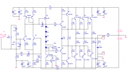
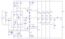
I have thrown out the design above and developed a new one. I have been working on this one (adapted from the KSA50) for about a year, off and on. Obviously, I didn't have these outputs in mind originally, but things change.
It looks good in simulation with low THD and very good stability.
Yes, I looked at the Leach idea early on and I can't see the advantage. More complexity when it should be less. I was following the TT thread also, and I couldn't understand the concern. I have used diodes to bias and monitor thermal condition before and didn't have a problem. These were just simple 1N4001's touching the heatsink.
See roender's RMC amp for his solution.
I have thrown out the design above and developed a new one. I have been working on this one (adapted from the KSA50) for about a year, off and on. Obviously, I didn't have these outputs in mind originally, but things change.
It looks good in simulation with low THD and very good stability.
Attachments
- Status
- Not open for further replies.
- Home
- Amplifiers
- Solid State
- Patchwork Reloaded: Circuit Optimization and Board Layout.