PB2 said:Are your input jacks isolated from chassis ground?
Hi Pete,
Well, when I finally get them put in they will be. For testing I have a shielded lead with an RCA on the end the plugs into my signal generator.
It seems to be a fluke occurrence, as it has only happened twice. I did read about it in another thread though, and I looked and looked but can't find it.
EDIT: You revised your post. The preamp for this will be my Yamaha receiver pre-outs thru the venerable DCX2496. This project is for my active three-ways.
This amp has the IEC connector for grounded connection. Ground tab goes straight to chassis off the IEC. I have my main star ground "floating", isolated from the chassis with a 100 ohm, 10 watt resistor.
The Yamaha Receiver (not even in the picture yet) is double insulated.
The Yamaha Receiver (not even in the picture yet) is double insulated.
You might want to unplug the amp and measure across the 100 ohm resistor to see if there is a short somewhere, perhaps through the chasssis.
PB2 said:You might want to unplug the amp and measure across the 100 ohm resistor to see if there is a short somewhere, perhaps through the chasssis.
Yes, that was one of the first things I did. It was fine.
This happened before on a completely different amp project with a different PS setup. That time I measured the resistor and it read 22K. This time (it just occurred to me and I went and measured it) his resistor measures ~10K. Weird, huh? What can make a resistor change value like that?
Anyway, I'm counting on the diodes to protect the resistor.
any capacitors near that bit of the circuit that could be putting charge across the probes and influencing the reading?
MJL21193 said:
Hi Mega,
Yes, the resistor is the only link with the common ground. There is one on each module.
Then the resistors probably got zapped when plugging something in, metal film resistors aren't very tolerant even to short time overloads.
An easy and pretty good solution is connecting all the input jacks to each other at the input jacks and then running one wire back to the star ground.
This will still prevent internal ground loops and decrease hum that can be gotten otherwise as leakage currents of double insulated equipment will flow through your 10 ohm resistors developing a voltage over them. The amplification is just 1x for this voltage but still degrades amplifier performance.
If the input jacks are not near each other some other method is probably needed though. The diodes should work but I'd use something beefier like 1N400x
BTW, most of the resistors in that picture I showed are from Sure Electronics too 😛
I'm counting on the diodes to protect the resistor
AKSA amps use the back to diode trick across the input ground
resistor. You should have no more problems.
Thanks for comment on CM thread. It was you,aksa,quasi,and
mr.self that provided valuble inspiration for a successful project.
OS
MJL21193 said:
Yes, that was one of the first things I did. It was fine.
This happened before on a completely different amp project with a different PS setup. That time I measured the resistor and it read 22K. This time (it just occurred to me and I went and measured it) his resistor measures ~10K. Weird, huh? What can make a resistor change value like that?
Anyway, I'm counting on the diodes to protect the resistor.
There are often problems in the gound wiring between different outlets, oxidized, loose wiring in the box, etc. You would not believe what I find in relatively new homes here in the US.
If you power amp soundly grounds the output ground to the third prong, I understand that you have a resistor but it could be shorted, and there is ground lift at the other device for any reason, then high current can/will flow through that 10 ohm resistor. I'd expect that it opening up causes some real disturbances in the amp and I therefore view it as a weakness if not done right. The design does not tolerate a high current fault for whatever reason between input ground and chassis ground.
See R201 here:
http://www.hafler.com/techsupport/pdf/XL-280_amp_man.pdf
Pete B.
PB2 said:You measured the 10 or the 100, or both?
Both. The 10R on the board is now 10K and the 100ohm 10 watt is just fine. All that the 100 ohm does is split the common star ground in the amp from the chassis. I have gone the extra distance and put a pair of opposing 1N4007 diodes in parallel with this now too. Just in case...
jaycee said:any capacitors near that bit of the circuit that could be putting charge across the probes and influencing the reading?
Hi Jaycee,
I'm not sure what you are asking. The 10 ohm resistor was pulled from the board and now measures 10K.
megajocke said:
Then the resistors probably got zapped when plugging something in, metal film resistors aren't very tolerant even to short time overloads.
An easy and pretty good solution is connecting all the input jacks to each other at the input jacks and then running one wire back to the star ground.
I want to maintain separate signal grounds for each module, so I won't join them at the inputs and I really don't want them going direct to the star ground. The problems with ground loops and hum that I have had in the past are neatly taken care of with this grounding scheme.
I will try the 1N4148's for now. If they fails, it isn't a big deal, as there won't be any damage done. Also I have literally tons of these but very few 1N4007.
ostripper said:
AKSA amps use the back to diode trick across the input ground
resistor. You should have no more problems.
Thanks for comment on CM thread. It was you,aksa,quasi,and
mr.self that provided valuble inspiration for a successful project.
OS
Gee OS, you are putting me in some good company! They would probably feel nearly as offended as I am flattered!😀
I'm just the grunt, the lowly assembler, putting others brilliance to somewhat good use so don't give me more credit than I deserve.
Ah, AKSA. That's not where I saw it, but if he does it, it should be ok.
PB2 said:
Hi Pete,
No short on the big resistor. It checks out fine. Like I mentioned above, I've added opposing diodes to this as well.
Yes, a thermistor instead of the resistor. That's an excellent idea that I'll use on future projects. In the meantime, I'm going to see how the diodes hold up. I have a feeling that they will solve this VERY chance occurrence.
A little more chassis progress.
Added input jacks:

Tidied up and re-twisted the power wires:

Added an aluminum wire race for the input leads. This should keep them in place nicely and shield them too.
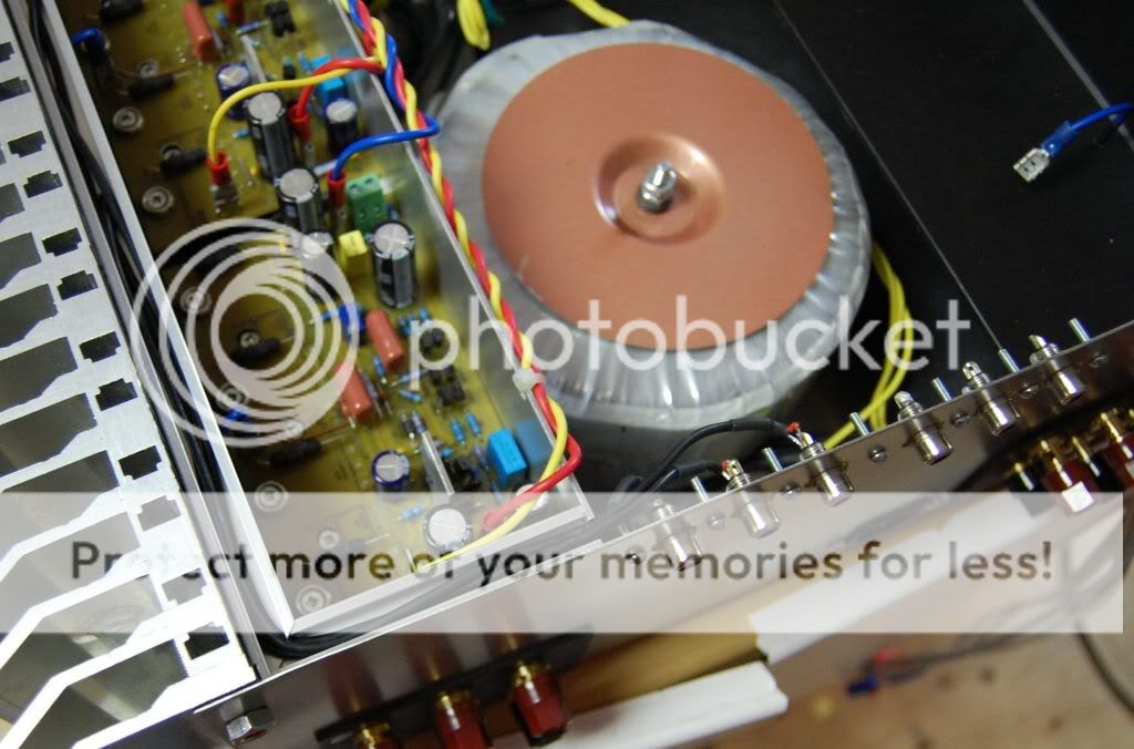
So, that's one side nearly buttoned up. Getting the other side done may take a bit longer. I picked up a big job (Hilton hotel at the airport) that will be stealing my attention for the next 2 months. Oh well, we have to eat, right? 🙂
Added input jacks:
Tidied up and re-twisted the power wires:
Added an aluminum wire race for the input leads. This should keep them in place nicely and shield them too.
So, that's one side nearly buttoned up. Getting the other side done may take a bit longer. I picked up a big job (Hilton hotel at the airport) that will be stealing my attention for the next 2 months. Oh well, we have to eat, right? 🙂
Your diode solution is probably going to be OK.
You don't need a wiring fault or something like that to zap the resistors in the first place. I've heard the Y-capacitors in double insulated equipment is enough to zap metal film resistors!
BTW, does the amp have DC protection hidden somewhere?
You don't need a wiring fault or something like that to zap the resistors in the first place. I've heard the Y-capacitors in double insulated equipment is enough to zap metal film resistors!
BTW, does the amp have DC protection hidden somewhere?
Lookin' nice ,MJL. Could that a be a 6 channel HT overkill amp??
When I get my case for Xmas, I'll save all that power for the front
channels and just use a robust chipamp for the rears..
Just like you I just had to try my amp with no Zoble, no
oscillations... but I put them in anyway.
As far as protection, when my thread is going (soon) One of
the first things going on will be my optoisolator super duper
protection circuit, feel free to use it when bugfree.
happy listening,
OS
megajocke said:Your diode solution is probably going to be OK.
You don't need a wiring fault or something like that to zap the resistors in the first place. I've heard the Y-capacitors in double insulated equipment is enough to zap metal film resistors!
BTW, does the amp have DC protection hidden somewhere?
Hi Mega,
DC protect is for chickens!! 😀
I have been running my big sub amp for several months without DC protection. I know, it's a stupid risk, but I'm too lazy at this point to include it. I will eventually open it up to do some other things and put one in then.
This project I didn't even consider it. Foolish me. 6 channels is a lot to monitor but the speakers this will drive deserve some protection, especially in light of current events:
As shown above, three of the modules are installed in the case (permanent like). Everyone knows that when it's harder to work on, that's when the problems start. Setting the idle current last night on all three, I left it to warm up for a half hour. When I came back and measured the current, one module read 0mV. Hmm, I look at the fuses - blown. Pull the module and start checking things. 2 output devices fried. Replace these, test on my lab supply and put it back in the chassis to test.
With no signal and no load, it is oscillating at ~3MHz. Not a big amplitude, but enough to burn the outputs, I guess.
I connect a Zobel and that kills the oscillation.
In the meantime, I check the other modules with no signal, no load and they are fine - no oscillation. I figure I'll add Zobels anyway, to all three boards. I do that and put them back in the chassis. Sure enough, no oscillation so I do some tests. Visible instability on the bottom half of the wave, especially approaching clipping. I get ready to check the next module (power off, drain supply, plug in the input). Power up and look at my fuses and 2 more are blown, this time a different module. These are fast blow, 5 amp fuses BTW.
Frustration is setting in. Why was everything working so well before, laying out on my bench? So, pull that board and sure enough 2 more outputs burned. These are really not very robust devices and if I had my time back I would have went with better ones. These are not even getting hot.
Anyway, where I am now is that I have increased Cdom to 100pF and installed Zobels on each board. I'm running one right now with no load and no signal to see if it wastes anymore of my money 🙂 So far, so good
ostripper said:Lookin' nice ,MJL. Could that a be a 6 channel HT overkill amp??
When I get my case for Xmas, I'll save all that power for the front
channels and just use a robust chipamp for the rears..
Thanks OS,
This 6 channel amp is for 2 speakers only.😱
An active three-way that I originally built active chipamps for, but now I want to use a DCX2496. Nice to have a bit more power too.
An externally hosted image should be here but it was not working when we last tested it.
Don't look at those feet, they are not staying (I don't like the way they look).
Ok, the amp seems fine now. Squarewave has a slight overshoot, but nothing at 1k. Stability is back and I've had it running a 1K sinewave into my 8 ohm dummy for about 30 minutes. Dummy is nicely heated up and the amp heatsink is slightly warm. Fuses are still intact.
So, 100pF it is. I thought I would lower it before when using the higher capacitance clamp diodes, but apparently that was not a good idea.
More than anything else, I value stability. I'll even sacrifice some sound quality (real or imagined) to achieve this.
I used the 2SC5200 / 2SA1943. I bought 25 of each. I have 3 pairs already burned out.
The reason for my handle (MJL21193) is I shorted the output on an amp with 4 pairs of these (with the MJL21194's) and the 15 amp breaker at my main panel tripped, but the outputs were fine. I'm not used to these finicky, rinky-dink devices - I need rougher stuff.
Next time it will be MJL4281A / MJL4302A
Are they Toshibas or are they another brand?
The onsemi MJL2119x are well known for their robustness 😀 I see arrownac.com has NJW21193 & NJW21194 for $1.87, they are the same chip but in TO3-P case instead of TO264. I don't know about their shipping charges to Canada but I'm sure it's cheaper than shipping to here, which was a bit expensive
The onsemi MJL2119x are well known for their robustness 😀 I see arrownac.com has NJW21193 & NJW21194 for $1.87, they are the same chip but in TO3-P case instead of TO264. I don't know about their shipping charges to Canada but I'm sure it's cheaper than shipping to here, which was a bit expensive
- Status
- Not open for further replies.
- Home
- Amplifiers
- Solid State
- Patchwork Reloaded: Circuit Optimization and Board Layout.