Set the Alarm Clock Adrian
Try it with the insulation on. It will probably work fine. Silver actually turns black from sulfides in the air. Put one of those anti tarnish strips in the box if you like. I tinned my wire along its entire length with 4% silver 96% tin solder. The dieletric constant of air and a vaccuum are nearly identical. I can get out my CRC handbook of Physics and Chemistry and look the number up if you like. Oh, I believe Steve McCormack of McCormack Audio and Bill Elliot of Counterpoint were the first one ones to explore the virtues of naked wire vs. teflon sleeving with the Wonder Wire the used in thier products. I am pretty shure that Steve used to listen to it for directionality. Wonder Wire used to come marked for direction when I bought it. Good reply but you are going to have to get up real early in the morning to catch me on wire and dielectrics. Just call me Mr. Peabody (way before your time I bet)
H.H.
planet10
By jove I think he's got it! Audio (log) taper for pot.
For you Canadians eh.....
100K STEREO POTENTIOMETER
100K stereo potentiometer.2-ganged pots with smooth "feel". 13mm (1/2") long, 6.35mm (1/4")diameter.
271-1732 $3.99
-- In Stock --
By jove I think he's got it! Audio (log) taper for pot.
For you Canadians eh.....
100K STEREO POTENTIOMETER
100K stereo potentiometer.2-ganged pots with smooth "feel". 13mm (1/2") long, 6.35mm (1/4")diameter.
271-1732 $3.99
-- In Stock --

the electrical parts - no problem, but where can I get these transparent boxes ?
Hockey pucks ?
Klaus
----------------
" ... no sports !" 😛
Hockey pucks ?
Klaus
----------------
" ... no sports !" 😛
Hello
I'm going to build this design except with a Vishay S102 and a Penny Giles pot and silver wire that I had laying around.
Should sound nice.
I love the case idea, think I'll look in the hockey store tommorow to see if they have any.
-- Aaron
I'm going to build this design except with a Vishay S102 and a Penny Giles pot and silver wire that I had laying around.
Should sound nice.
I love the case idea, think I'll look in the hockey store tommorow to see if they have any.
-- Aaron
Harry,
Can you post the schematics for the Wayback Machine? I always wanted to build one of those.
I thought Radio Shack had a semi-expensive Alps pot available at one time. Haven't seen it lately.
The hockey puck: Somebody at Headwize built a headphone amp into one. Canajan, eh?
Can you post the schematics for the Wayback Machine? I always wanted to build one of those.
I thought Radio Shack had a semi-expensive Alps pot available at one time. Haven't seen it lately.
The hockey puck: Somebody at Headwize built a headphone amp into one. Canajan, eh?
A passive preamp?? Give me a break.
Why are we calling a dual volume control a passive preamp??
The least we could do is build such a device it in a enclosure that offers some shielding to RF and other interfearance. It may add to the cost a little but the beneifits far out weigh the problems associated with plastic un-shielded boxes.
John Fassotte
Alaskan Audio
Re: A passive preamp?? Give me a break.
John,
ever tried to omit shileding and then compare it to shielded mode?
listened to it?
I did. Since then i omit shielding if possible. With housings and with cables.
Even if you offer it a s a product, you can offer a shielded and an unshielded version (and charge more for the latter 🙂 ... 😛 )
Originally posted by alaskanaudio
Why are we calling a dual volume control a passive preamp??
The least we could do is build such a device it in a enclosure that offers some shielding to RF and other interfearance. It may add to the cost a little but the beneifits far out weigh the problems associated with plastic un-shielded boxes.
John,
ever tried to omit shileding and then compare it to shielded mode?
listened to it?
I did. Since then i omit shielding if possible. With housings and with cables.
Even if you offer it a s a product, you can offer a shielded and an unshielded version (and charge more for the latter 🙂 ... 😛 )
I never had a chance to compare shielded and unshielded version of a same piece of equipment. Are you suggesting that amps and preamps built out of wood or plastic would sound superior to their aluminium versions?
from webster:
passive: of an electronic element : exhibiting no gain or control.
amplify: to make larger or greater (as in amount, importance, or intensity) : INCREASE b : to increase the strength or amount of.
I would like to request suggestions for an alternate name for the types of circuits described in this post.
I ain't got no idea of what to call it. 🙂
Stephen
HPotter said:Are you suggesting that amps and preamps built out of wood or plastic would sound superior to their aluminium versions?
I haven't gone that far, but Al or Cu or brass generally sound better than steel.
dave
To shield or not to shield.
In my opinion all audio circuits should be shielded from external influences for maximum performance and purity. Use shielding if you want o keep the actual audio signals as pure as possible.
Without shielding it possible for a circuit to work properly or fairly well in one physical location and not at another. It all depends on the environment that the equipment is located in.
For example I live at a location that it less than a half mile from a fairly high power television transmitter operating on channel two (roughly 54 MHZ). The video carrier is AM modulated and is picked up by any unshielded device and partially demodulated.
The demodulation of the AM modulated video signal causes bias changes within the equipment that occur when scene changes occur. These changes can be substantial at times in line or low-level circuits. They will also appear as a hum level that changes with video carrier modulation.
What it comes down to is this. The more critical you are the more critical the construction techniques become. Nothing should be overlooked if possible. Wood over metal housings is ok to dress things up. But making a chassis out of wood without any type of shielding for the actual circuitry is not. Acceptable building standards are of course are determined by the builder. I used to know a fellow who built everything in cardboard boxes and was perfectly happy with the results..
My advice remains, shield everything as best as possible from the environment that the equipment is located in for maximum performance. At least add enough shielding to keep low level 60Hz power line noise and harmonics out of audio circuits.
The type of material used for shielding will depend on what you desire to do. Aluminum works fine for chassis and is more or less a standard. But is you need to stop magnetic fields from entering sensitive circuits then some steels are much better. Brass and copper sheets are easy to solder together, as is double sided printed circuit board material. These may not look as good as other methods but can provide very effective shielding.
John Fassotte
Alaskan Audio
Shunt attenuator?honeycombaudio said:I would like to request suggestions for an alternate name for the types of circuits described in this post.
Shielded audio
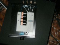
Much to your surprise I bet, I agree. I use RC filters on the input almost all audio circuits. I also like ferite clamps on power cables and audio cables. I highly disagree with designers that build very high bandwidth amplifiers and preamps. RF frequencies get demodulated by audio circuits and can form distortion products down to DC. I also believe that FET circuits suffer less from this than bipolar. The passive has very short signal path and I have not noticed any effects from RF or 60Hz in my setup. I feel it is much less likely to pick up noise than a pair of unshielded interconnects. It is a bit of cosmic justice getting nailed on this since I did EMI and signal integrity in my last Telecom gig. In self defense I submit this picture of my reference preamp with input RC input filter, battery biased shielded wire, and a steel chassis ... Good advice and input.
H.H.
Attachments
Of course that circuit could be improved as well. I didn't mention that on the previous preamp because it supposed to be cheap and easy to do. But when I see a reference unit I can't sit quiet. Why not to mount potentiometer at the back of the unit and connect it to input/output jacks directly with very short wires. Then install on the potentiometer's shaft 10" extension to the front plate. That way you eliminate the wires and no matter how good they are they still have influence on the sound. You might even get rid of the batteries. I didn't quite understand what they do. Would you elaborate more on that subject. And what about those blue dots in corners. Did you put them "just in case" or you actually made comparison with and without. I wonder what was the actual difference.
Don't take me wrong. I like to experiment with different materials and techniques and I was just hoping to learn something.
Don't take me wrong. I like to experiment with different materials and techniques and I was just hoping to learn something.
Reference Passive
Yep I could have put a shaft extension but the enclosure was home to an active preamp at one point might be again. The blue dots are chassis damping with EAR material. Actually at this point the chassis uses constrained mode damping and the white portion is rigid polyethelyne with EAR material between it and the chassis. The wires are also clamped with EAR material to this polyethelyne block. The battery bias is between the wire shields and the ground and signal wires. The shields carry no audio currents and are tied together at only one end and connected to the RCA jacks ground via a 0.1uF MIT cap that also carries the bias voltage. Jacks are Cardas rhodium. The attenuater is a series shunt cofiguration With Caddock TF 20 resistors and a 100K Alps Black Beauty pot which is also damped with EAR material. The inputs have Holco resistor/Seimens polystyrene caps input filters to terminate input interconnects resistively at RF frequencies. This makes sure that the source is not driving a reactive load at RF. The input filters also bandwith limit RF signals the could get through to the power amp. All the wire is stranded silver clad OFC copper with teflon dielectric. Solder is 4% silver 96% tin. Even the with 15" signal path it sounds pretty cool. The are several battery biased cables on the market. It even sounds better to bias digital cables! I have bulit dozens like that.....
H.H.
So if I understand it correctly you apply battery voltage between ground and the shields with capacitor across battery terminals. How important is the value of the voltage. I'm using Kimber Illuminations D-60 interconnect with BNC on my digital rig. Can I apply that technique and how should I do that? BTW if you disonnect the battery how the sound changes?
Battery bias
I will have to draw a schematic and I will try to get around to it this week. I use 100V ERO polypro caps since they are small. I AC couple the center conductor of the digital cable. Connect a 1 Meg resistor to the center conductor and bias with a nine volt battery. You have to let the wire settle for a few days since the biased wire has to go through break in with the voltage across the dielectric of the cable. I have not biased the D-60 before. I will have to find it around here somewhere. I used to talk to Chris Sommevigo all the time and he traded me a D-60 for some equipement I was selling. I have played with bias from 5 volts to 40 Volts to high a voltage will screw up the sound. I am not going to tell you what I hear but you can try it and tell me what you hear.... The theory is the wire becomes more rigid from the electrostaitic force and that the polar molecules become aligned from the polarization voltage. I am not a material scientist but this sound like reasonable factors. I might have some caps left, Email me and let me know how you plan to do this mod.
H.H.
Reference Passive attenuator
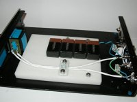
I present the Nimbus 2002 Reference passive attenuator to help passify (whoops.... a pun, I promise not to do it again) HPotter's concern over wiring length. I also unsoldered the leads from the Caddocks and soldered wires and input RC filter parts directly to the pads on the resistor substrates. That's half the wire length and 10 less solder joints! Now for a week of break in.......
H.H.
Attachments
- Status
- Not open for further replies.
- Home
- General Interest
- Everything Else
- Passive Preamp