Simulations VI.
Please take a look at the graphs below:
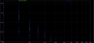
Blue is still the circuit with No feedback.
Green is the circuit still with 15 dB feedback, but now with Vds compensation, roughly corresponding
to the loss of Vds due to the insertion of degenerative resistor element in the
Source circuit.
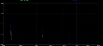
As can be see, there are no higher order harmonics present, and the feedback
factor is still 15 dB, roughly corresponding to approximately 15 dB of lower
amplitude on the 2nd, 3rd, 4th and so on.
This can be seen on the second, zoomed-in graph.
Please take a look at the graphs below:
Blue is still the circuit with No feedback.
Green is the circuit still with 15 dB feedback, but now with Vds compensation, roughly corresponding
to the loss of Vds due to the insertion of degenerative resistor element in the
Source circuit.
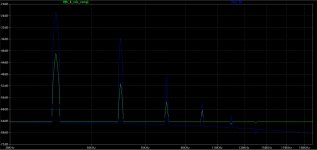
As can be see, there are no higher order harmonics present, and the feedback
factor is still 15 dB, roughly corresponding to approximately 15 dB of lower
amplitude on the 2nd, 3rd, 4th and so on.
This can be seen on the second, zoomed-in graph.
Attachments
Of course these are just simple simulations and the reality might be different.
However, I believe feedback is not the cause of these higher order harmonics shown in the graph of post 400.
I do not have access to real THD analysers, which would be very beneficial at this point.
Please share your thoughts, or your wonderful AP thd analysers.... thank you all for your help.
However, I believe feedback is not the cause of these higher order harmonics shown in the graph of post 400.
I do not have access to real THD analysers, which would be very beneficial at this point.
Please share your thoughts, or your wonderful AP thd analysers.... thank you all for your help.
Last edited:
Simulations VIII
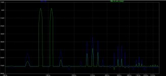
The high frequency IM test is much more demanding than single tone tests.
They would expose gain irregularities much better.
So here is the simulation of 1W into resistive 8 ohms of 17 kHz and 20 kHz signals:
As before:
- Blue trace is the non feedback circuit.
- Green trace is the circuit with 15 dB feedback circuit and Vds compensation.
The no feedback circuit has problems reproducing this mixture as evidently
depicted in the graph below.
The highly bent transfer function of the non-feedback circuit more readily
creates sidebands of the input signal, whereas the circuit with 15 dB feedback
is more linear.
Attachments
Alexiss, your posts are interesting, but they are not specific to XA25 nor Pass labs, if I understand them correctly. Why don't you open another thread about this feedback vs non- feedback topic, so that the people in the future can follow your whole experiment much easier. 🙂
🙂
Thank you for your response plasnu.
Well, the document was published by Pass Labs and that is how we got into it here, but I think
you might be right. Let's get back to the main discussion, that is the circuit of XA25
btw: I think there already is a thread on this 🙂
------------------------------Alexiss, your posts are interesting, but they are not specific to XA25 nor Pass labs, if I understand them correctly. Why don't you open another thread about this feedback vs non- feedback topic, so that the people in the future can follow your whole experiment much easier. 🙂
Thank you for your response plasnu.
Well, the document was published by Pass Labs and that is how we got into it here, but I think
you might be right. Let's get back to the main discussion, that is the circuit of XA25
btw: I think there already is a thread on this 🙂
Last edited:
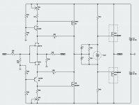
Conceptual Schematics continues II
There are a few things left, that is, the bias generators, and the DC offset adjustment means.
But there is no info on XA25 on the net, and we do not even know how it sounds - since this is
a fairly different, "simplified" or "optimized" version of the other Pass Labs amplifiers.
The bias generators in the attached pic above would certainly work (with some mods to define start-up conditions),
but it appears Pass Labs might be using a different generator.
Your suggestions are most certainly welcome.
Have you guys found any other reviews?
Last edited:
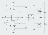
It is all described in the Sony II articles at First Watt.....🙂)
-------------------------------------
The Front End presented in the Sony articles and all other Firstwatt papers (wonderful documents btw - thanx Mr. Pass)
are all incapable of producing such low thd figures presented in the Pass XA-25 manual without slight modifications.
But i agree that the VFet front-end very closely resembles that of XA-25.
I think Mr. Pass made some comments about it earlier.
I think the conceptual schematics presented above (the last one) might be very close to the original.
There are two issues that need to be solved however:
1. Bias generators.
2. DC offset compensation.
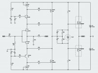
It's pretty much identical to mine except you've used caps to drop open loop gain. Not a bad idea. It would probably be better if R21 and R23 were fixed resistors and R20/R17 were trimpots.
I don't particularly feel good about posting circuits that attempt to copy a circuit in a thread labelled as such, zen mod and others tend to be a little more discrete/subtle about it, hence the reason for creating another thread with a completely ambiguous title.
I don't particularly feel good about posting circuits that attempt to copy a circuit in a thread labelled as such, zen mod and others tend to be a little more discrete/subtle about it, hence the reason for creating another thread with a completely ambiguous title.
Last edited:
Where I work we'd be put in jail for a very long time for sharing this sought of thing.
I struggle to know what's appropriate.
I struggle to know what's appropriate.
You probably mean "this sort of thing".... this sought of thing....
"Sought" has a different meaning ( sought Meaning in the Cambridge English Dictionary ) although the pronunciation is similar, like "court" and "caught" 😱
You probably mean "this sort of thing".
"Sought" has a different meaning ( sought Meaning in the Cambridge English Dictionary ) although the pronunciation is similar, like "court" and "caught" 😱
Wow.
That was impressive.
Hahaha
- Home
- Amplifiers
- Pass Labs
- Pass XA25?